The Thorens TD 160 – basic modifications and maintenance, and Rega tonearm upgrade

Last Modified: 5 Jun 2012
Notes 2011 – 2012
Since this was written the arm has also been rewired with Litz wire, see Rega Arm Rewire.
T
HIS IS A second one that I acquired Autumn 2007 from eBay. The original one I bought back in late 1975.(!) They're both early 'Mark I's' (that is, the first TD 160 model, preceding the Mark II etc.). I got a second one just for a spare (or rather I decided to keep the original as the spare and use this one). Both use the TP 16 tone-arm and feature a sprung floating sub-chassis on which both the platter and tone-arm are mounted.
This one is earlier manufacture than my original. The main differences between them are that the later one has twisted pair wire leads in the tone-arm to connect to the cartridge, whereas the earlier uses miniature screened leads. The later twisted pairs have lower capacitance, also a special screened enclosure for the output lead interconnections. Also, the later model has better earth wiring, albeit still using the screen of the right-channel lead to earth the chassis through the amplifier's input socket screen, since the mains lead remains 2-core only. Hence the early one (this one in the pix) was modified to have the same, and with the further modification of a separate earth wire to connect to an earthing post on the pre-amp chassis (mains earth), instead of down the signal lead screen. This is simply because, in the case of a genuine mains short-circuit accident, there could be several amperes flowing through this connection! Also it obviates possible hum-loop problems by entirely isolating the signal earths from the chassis altogether.
 This deck also came with a Nagaoka MP11 MM (moving magnet) cartridge. The stylus options were MP10, conical; MP11, elliptical, and MP11 elliptical 'Boron'. Though it seemed perfectly okay, a short while later a new MP20 stylus was acquired just to be sure.
Siting The Turntable

 To minimize vibration effects, the deck is installed onto a solidly fixed, wall-mounted shelf, built into an alcove. (But I have since moved house, and so at the moment it's on a media unit, and 3 adjustable speaker spikes.) The corner wall to the left in the pix is actually a chimney stack, so plenty solid! Furthermore...
 ...the shelf includes a 3-point screw mounting system so that the deck can be made exactly level by adjustment of the screws. The entire turntable is supported on just these three screws.
 Clawed 'T'-nuts are hammered into the shelf topside, of the type normally used to mount loudspeaker drive units into baffles, such as the example below, these were Order Code L34AA from Maplin Electronics:
 Screw heads are simply twiddled from underneath...
 ...while using a spirit level on the platter (in a sprung sub-chassis system, the platter is not necessarily level just because the main top deck is).
Replacing The Bottom Panel
 However the standard hardboard base panel is not strong enough to bear all the weight of the deck while resting on three screw tips, and will just bend (also affecting the sound quality by the panel becoming another vibration sensitive component if supported in this way). Ideally, therefore, it should be replaced with a much more rigid copy made from 12mm thick MDF. Use the original panel as a pattern.
 Before final assembly, base board is edged with black gaffer tape...
 ...and secured to main unit with M4 x 25mm c/sk chipboard screws (using the original screw hole positions).
Earthing Modifications
 On the early TD 160, remove this wire link between right channel (red) signal screen terminal and sub-chassis.
 Also watch out for this metal tab on top deck (unsprung chassis) soldered directly to the right channel screen terminal. Unsolder it and bend it back away from the connector block.
Note thin wire at bottom of pix is special earth wire for the tone-arm tube only, it can remain connected to the right channel screen as shown.
 Fit a new light gauge, stranded wire connecting the (sprung) sub-chassis to the (unsprung) top deck plate, between the original sub-chassis screw connection and...
 ...a spare hole near the motor. Scrape around the edges of this hole to ensure good electrical connection. Fit with M4 screw and nut. Note forked spade terminal includes thicker earth lead which exits the rear of the unit and...
 ...is about the same length as the signal leads, and has another spade terminal on the end which...
 ...ultimately connects to chassis earthing post on the rear of the preamplifier module. Note also the wires are soldered into the spades as well as crimped.
 In use, the sub-chassis hangs on three cone-shaped springs. These only begin to work once the full weight of the complete platter in present...
 ...only then does the sub-chassis break contact with the underside of the upper top plate, and the sub-chassis is suspended on the springs. In total the platter weighs about 3kg.
Mechanical Servicing
 Which mainly consists of putting a couple of drops of engine oil into the bottom of the blind bearing housing (but don't turn the deck upside down afterwards!)...
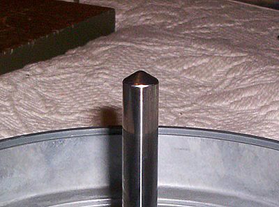 ...so that the pointed tip of the platter hub-centre shaft is running in a little puddle of oil. This tip rests on the bottom plate of the bearing housing but with a very small contact area and hence minimum friction, still, over time it manages to wear a little dimple into the bottom plate if running dry.
 Before reinserting also apply a smear of engine oil to the sides of the shaft for the bronze bushes. The hub-centre operates as a drum for the belt drive.
Note on the later TD 160 the hub-centre may have a plastic retainer ring on the shaft with two hooks on the sub-chassis to prevent it being withdrawn. To remove the hooks there is a screw on the underside.
 You might also want to try a drop of light 3-in-1 oil for the motor shaft bearings. The bottom one is easy to get at...
 ...whereas of course the top one is hidden beneath the friction clutch belt drive. This is retained by two tiny Allen key grub screws (in top brass bit, observe visible hole for one of them), but which I didn't disturb. Instead I carefully inserted a narrow strip of card beneath the large brass washer visible at the bottom, up to contact with the actual spindle, with a drop of 3-in-1 on the end.
Changing To Rega RB 250 Tone-Arm
A year later the original TP16 tonearm was replaced with the Rega RB 250.
This is what a stock RB 250 looks like when you get it:

This is it after all the mods:

These include a solid brass end-stub and counterweight, and a Michell "finger nut" or sleeve nut that is both narrower and can only be made "finger tight". Also a solid oak "arm-board" that replaces the TP16's built-in item, and a separate earthing wire that is not connected to the left channel screen.
Before all that though, further modifications to the chassis.
Prepare to remove TP16 tonearm ~ unsolder / unclip signal leads and remove audio leads connector block:

Remove remote cueing control device cable:

Remove the TP16 tonearm (3 screws):

Remove the cueing device control in its entirety (remaining hole filled with black plastic 3/8's inch blanking plug):

Remove all three sub-chassis springs, most importantly "losing" the foam insert bits (i.e. don't put them back on reassembly!):

Then sub-chassis plate is free ~ though need to unscrew one spring pillar to get it out:

Tonearm base mounting hole needs to be made bigger to accommodate new position of the Rega's mounting pillar. Note the Rega arm is longer so in order to achieve the 222mm distance from platter spindle centre to the Rega's vertical pivot centre, the latter's centre point has to be about 6mm further out to the right and further back.

Rega arm will fit like so, or thereabouts:

The bottom of the chassis and sub-plate and the insides of the wooden plinth are covered with self-adhesive 'Dynamat' damping material as for speakers mounting in cars:


On reassembly, the spring nuts are adjusted so that the bottom of the platter is parallel to the top panel by about 5mm all around. This has to be done with the arm installed as well so that the all up weight is present as it would be in use.
Modifying The Rega Arm Earthing
Below ~ normally the arm earth wire (black) is connected to the left channel screen (blue), then there is a metal strip that hangs down the side of the moulded plug-in insert to contact to the hollow pillar. The 'plug' has a small cricular PCB with five pads on it (it is retained by a small grub screw in the side of the pillar base):

The metal strip is removed and the black wire moved to the now unused free fifth pad. A separate thin multi-stranded earth wire is then attached:

This is ultimately terminated at the earth wire solder tag on the sprung sub-chassis, and goes out to pre-amp earth post at mentioned earlier.
Finished arm in situ ~ note old armrest is removed:

Setting Up Adjustments
Note the tracking weight is adjusted by shifting the counterweight position directly, and locked with its tiny Allen grub screw, and has to be set using a stylus balance. For the MP10 the tracking weight is 2 grams.
The Vertical Tracking Angle (VTA) is set by adding large washers to the top of the armboard to raise the arm pillar. Given that the armboard is 12mm thick (as the TP16's plastic original) an extra 4mm was needed.
Below ~ checking offset (zenith) angle and overhang using a Stevenson type 2-point protractor. The cartridge should be square to the grid in both positions. This makes sure that the stylus is as much as practicable 'parallel' to the groove at all places on the record. If it is not then severe harmonic distortion may result, especially in the upper-midrange and treble bands, due to the angle of error.

This is best illustrated by the following diagram:

Increased error of offset angle (zenith) results in a misshapen output waveform from the cartridge that is not a true representation of the groove shape. In the upper-mid and treble bands this creates overtones that amount to harmonic distortion, making for a bright or rich sound. Of course you might like it that way! It is most likely that a badly tracking cartridge that is then aligned properly will have a noticeably reduced treble output. These were actually overtones that should not be there. For a complete discussion see the original paper that this diagram came from, in PDF Analytic Treatment of Tracking Error and Notes on Optimal Pick-up Design , by H. G. Baerwald. It's pretty heavy going but gives you the gist, plus an interesting comparison between the foregoing straight arms and their consequent problems, and the later offset arms and why they are superior.