Guzzi Rebuild aka Guzzi Jobs 2013
Last Modified: 11 July 2014
C
OMPILED FROM A TOPIC originally on the Moto Guzzi Club GB forum (now removed. Hence this web page).
Topic: Guzzi Jobs 2013
Posted: 12 May 2013 at 19:56
Got off me bottom to start doing something last week, so started at the front ~

^ ... put the new discs on, plus new pads and bleed brakes.

^ ... mentally psycheing myself up to have a go at the wiring ...
This bit from 'Cali Type Sidestand' topic ~
Luxexterior
MGCGB Member
Posted: 01 Nov 2011 at 09:26
Originally posted by Don-Spada
If you know someone with a Bonnie or comando, it might be worthwhile just offering one up to the old Spada mounting bracket to see how it would work. Anything would be an improvement on the original thing. That was about as much use as a chocolate fire guard!
If you know someone with a Bonnie or comando, it might be worthwhile just offering one up to the old Spada mounting bracket to see how it would work. Anything would be an improvement on the original thing. That was about as much use as a chocolate fire guard!
I've seen better chocolate fire guards!
Me
Posted: 12 May 2013 at 18:57
Had another go at this the other day. The trick was how to lower the foot in the retracted position enough so bar doesn't foul the gear pedal ~ my previous version had a slight bend put in it near the pivot end, not a good idea as it turned out, because it then made the foot too low when extended!
Had another go with stand No. #2 (courtesy of eBay) ~

The trick is to use the lower M8 bolts only, initially, which allows the mount plate to skew so the foot drops quite a bit. M6 bolts and nuts may be inserted through the upper bolt holes. On mine the gear pedal still needed raising at least half an inch, but can now be fully depressed without fouling:


Just needs some sort of buffer on the silencer.
Tried gear pedal with my shoes on and it seems quite OK, suggests it was set on the low side hitherto. It was certainly lower than the brake pedal, which incidentally I also raised a bit as was not a lot of clearance between it and the footrest actually.
So if you squint along each pedal rubber with the frame rail behind, the height (of both) is now about a quarter inch higher than central to the rail. If that makes sense.
PS: these are T3 style footrests pedals and exhausts.
Posted: 26 May 2013 at 20:09
Bijou update ~ upon swapping the gearboxes it would seem that the original one (came with bike) had a long gearchange linkage lever (what the pedal connects to); on the replacement box's one the distance of the linkage point to shaft centre is half an inch shorter! It's off a Cali 3 ~ are these levers a common 'standard length' or are Cali ones shorter or is the 'long' version yet another 'special bit' that was unique to this particular bike?
Could be, 'cause it had home made rear-sets and pedals, the pedals were quite short so this would be a way of increasing the leverage, or if you prefer, the distance the pedal moves up and down.
Having the shorter Cali 3 one means that now the pedal height can be made exactly the same as the brake pedal, AND still leaves ample clearance between itself and the Cali sidestand when fully depressed!
Posted: 12 May 2013 at 20:12
Preparatory to gearbox swap, got it out of the shed to get it ready.
Needed quite a degreasing session (used half a jar of petrol/paraffin mix), then treated to new stainless plugs and screws.

Then got the pushrod gubbins out (needed tapping with a hammer), cleaned and regreased and re-installed. It can now be moved with finger pressure!
Next wanted to dismantle and grease the lever pivot, but the pin had rusted solid. Soaked it with penetrating fluid and left it for half an hour or more, then see if a hammer could move it. Eventually, but had to tap it both directions several times to free it. Ha I gotcha now you little so-and-so! That's it come to daddy! Success

Cleaned the rust off with emery cloth and reassembled with grease and a new split pin.
Posted: 12 May 2013 at 20:29
Spent most of today getting this off ~

One very old and tired (and filthy) loom. Several wires have gone hard and some colours have faded.
Fusebox was so disgusting it had to be washed in petrol ~ much better now!

Rectifier (not shown) checked out good on the Fluke's diode test function. I discovered it does not have the 2 diodes installed for the stator coils centre-tap (blue wire from alternator), there's tracks for them on the PCB, but unused! No point having the blue wire then is it? It am do not go nowhere.
Oh look what I found! The empty shell of what was a starter relay.

Posted: 15 May 2013 at 12:47
Nearly got a new main loom now ~ here a test plugging together to see if all the wires are there ... which they seem to be ....

Posted: 15 May 2013 at 12:54
Fusebox ...

... rectifier ...

... flasher unit and power socket

Posted: 15 May 2013 at 13:04
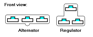
Regulator, with the alternator's connectors behind. No blue wire 'cause there ain't no connection for it on the rectifier. So is omitted.

Starter relay. White-brown (starter button) 'cause couldn't get white-black (the 'correct' colour); red-yellow (output to solenoid) 'cause ran out of red. Supply side of relay coil is taken from ignition (white) hence starting is defeated if kill switch is off.

Posted: 15 May 2013 at 13:10
Tail lights connectors, starter solenoid and neutral switch. Game ~ which colour does what?

Rear brake switch. The boot is still in excellent condition!

^ Note I've got sleeve insulators on the female connectors as well.
Quite a bit to do still.
Posted: 15 May 2013 at 15:25
As a matter of interest, in case anyone was wondering, the special connector 'covers' can be removed and reused, as you might have noticed in the above....
The trick is to insert something like a bradel or thin rod into each of the coloured areas from the front, to flatten the connector's locking tab, the connector can then be pulled out of the back.
The regulator one has embossed on the back 'D–' (black / frame) 'DF' (violet / alternator field rotor) 'D+' (red / rectifier). The other just has 'GERMANY'
HTH
Posted: 15 May 2013 at 15:36
Appendix ~ on the subject of special covers again ~ naturally the connectors had to be replaced with new ones with the same type locking tabs, and it so happens that the ones that come with these were identical fit:
8 Way Electrical Connector (6.3mm)
guzzibear
Posted: 18 May 2013 at 12:24
You may know this BUT the wires to the alternator need to be heat proof as it gets hot in there and WILL melt any plastic insulation OR connectors.
I used fibre glass insulated over heat resistant insulation for the wires and a Bakelite type connector. They are used in things like transformers and have stood up over 10+ yrs.
The first time I did it the alt failed after a few hundred miles due to everything basiclally melting. If you have NOT already got it there is a plastic spacer ring that fits to the back of the altenator cover to allow better air flow.
Me
Posted: 18 May 2013 at 20:22
As far as I can tell the original yellow wires look very unspecial, no extra sleeving, and the 3-way connector appears to be plastic, in fact identical to that at the rectifier end.
So I dunno

Mind you always have had the spacer ring.
Admittedly, the 3 yellow wires were a bit hard. But then again, wires in several other places were a bit hard as well due to heating effect on the insulation, notably the 3 for the ignition coils (white - green - red).
Posted: 18 May 2013 at 20:32
Took advantage of the dry weather today, as was supposed to start raining in the next day or so, to get closer to the gearbox. Pannier frames and carrier off, and rear mudguard, carbs and starter motor. And breather collector gubbins and battery base.
Theoretically (at least) that means swing arm out next then should be able to crab the frame.
If on the other hand it rains I got plenty to do now under cover.
Reason for edit: typos
Edited by Mike H - 18 May 2013 at 20:33
Posted: 20 May 2013 at 17:45
Gearboxes swapped yesterday! Only took all day!
Crabbing the frame ...
If you are contemplating gearbox removal be warned you need to virtually strip down to the bare frame (and the frame separated) EVERYTHING has to come off, there are no short cuts. Even the main stand has to come off, I thought it could be left attached but no, it does not allow gearbox to be slid backwards far enough to free it.

Posted: 20 May 2013 at 17:56
Original gearbox extricated ...


Next, need to swap over splined centre boss (Pete Morecombe asked "do you need the splined boss" ~ "no my one was brand new in 1995" ~ "OK I can take it off") ~ despite having what I thought were 'the correct tools' this job whiled away a merry hour or so (not) ~ the nut bent the pegs on the special socket so I had to straighten them again in a vice, finally succeeded getting it off by using the socket in an impact driver (which includes a 1/2" drive for sockets). Why do people have to do these things up so blasted tight? (Wasn't me who put it on last time!)

Here's a tip, just to make sure find ALL the ears of the tab washer and knock them flat, there may be some still gripping the nut at the back, I think that was partly my problem. I tapped them down with hammer and screwdriver until I could see them ALL flat against the splined boss.
NB the nut is chamfered on the back, so the ears are normally raised up behind it at an angle, if not then on reassembly you won't be able to get underneath whichever one it is to bend it over to lock the nut. Guess how I know. Had to take it off again and bend all the ears up so it ends up looking like a dished shape.
Posted: 20 May 2013 at 18:33
Next, try to install prepared gearbox No. #2.
There's something really weird going on with the pushrod, when I push the box onto the studs the outer thrust part with the O-ring on is pushed out the back, as though the rod is too long, or the gearbox is too short ~ WTF?
Eventually I go get the pushrod gubbins out of gearbox #1 and try that. Better. The actual rods appear to be the same length, maybe #2 has extra shims or something? TBH I wasn't happy with #2 ~ the rod binds in the inner thrust piece, so maybe it wasn't fully home to the bottom...
Much swearing later I think I might now have it screwed on for what is hopefully the last time.... The outer thrust piece with O-ring is still slightly proud ~ I've only just now looked at the gearbox lever adjustment photo in my MG manual and it's exactly the same there! So must be right then. Of course I didn't take any notice of what No. #1's set-up looked like before I took it off (why would I? ) ....

Posted: 20 May 2013 at 18:47

Close-up of pushrod end ...

... and photo from workshop manual ...

Posted: 20 May 2013 at 18:50

Posted: 20 May 2013 at 18:59
Didn't do much today, cleaned up and polished and greased the pedals and put them back on and adjusted, couple of new frame bolts and spent must be AN HOUR straightening out the 'acorn' thingy for the speedo cable so it can be regreased and go back on. Clutch cable oiled, and linkages greased and adjusted.
guzzibear
Posted: 20 May 2013 at 21:42
Mike swap the 13mm nuts on the gearbox to the engine for acorn ones .... saves them seizing look better too Good job ... one thought on clutch pushrod .... the thrust bearing at the clutch end was set in correctly??? Guess HOW I know that one!!!!!
Me
Posted: 26 May 2013 at 20:10
Also on Cali Sidestand topic ~
Bijou update ~ upon swapping the gearboxes it would seem that the original one (came with bike) had a long gearchange linkage lever (what the pedal connects to); on the replacement box's one the distance of the linkage point to shaft centre is half an inch shorter! It's off a Cali 3 ~ are these levers a common 'standard length' or are Cali ones shorter or is the 'long' version yet another 'special bit' that was unique to this particular bike?
Could be, 'cause it had home made rear-sets and pedals, the pedals were quite short so this would be a way of increasing the leverage, or if you prefer, the distance the pedal moves up and down.
Having the shorter Cali 3 one means that now the pedal height can be made exactly the same as the brake pedal, AND still leaves ample clearance between itself and the Cali sidestand when fully depressed. Job's a good 'un.
Posted: 27 May 2013 at 16:02
Swingarm is now ready to go back on, after a clean up and a bit of Hammerite smooth to keep the rust at bay.
UJ and support bearing were in perfect condition, save the slight fly in the ointment viz the boss being loose in the bearing (they all do that Sir), re-inserted it with a dollop of nutlock and let it set, it will come loose again of course with use but if the bearing spins freely (which it does) it's really not a big issue.

Again driveshaft is practically perfect, circlips still tight and coupling sleeve good (these had been renewed sometime earlier), just needed a quick rinse in petrol/paraffin followed by a regrease. The box oil seal has a bit of a weep though, so waiting for a new one at the mo. It may be scoring around the o/p shaft under the seal is the main cause really, this was caused by swarf in the oil due to a drain plug stripping its thread some time ago. Moral, do not give drain plugs too much welly when tightening up. (Not me, previous owner, he knew of only one torque setting which he applied to everything, 100 lbs/ft). Anyway seems the seal is a bit 'loose', so to speak, so as it's easy to get at just bung another one in.

Battery tray and carrier de-filthed and painted, and now got new batt straps as well! Will be the first time I'll have actual usable working ones...

Posted: 27 May 2013 at 20:35
Now here's an interesting thing (or mildly interesting) one of the last things I was doing was re-attaching the plastic rear mudguard section with SS fasteners and installing the electronic regulator.
Note this needs two M6 nuts added behind its bracket to act as stand-off spacers, otherwise the top of it fouls on the upper frame strip so it leans outward.
Also, the foward bolt has to be a flat headed bolt (e.g. not Allen screw, that's too thick) because the head end has to be on the outside of the battery compartment, i.e. on the bracket of the regulator, if not, it seems to me it won't give you enough room to plug in the 3-way connector! No way will a nylock nut plus a bit of bolt sticking out nor I think an Allen head! This caused much faffing about and darkly muttering ...
But here's the interesting bit ~ how the earth wires were connected in this area.
Left hand side, 2 M6 earth tags, rear lights, and regulator ground, both go to the hexagon pillar the sidepanel clips onto. Nut and washer for this pillar is right against the frame, so if clean metal underneath a good frame connection is assured.
Righthand side ~ 2 M6 tags, rectifier negative, and, what was brake fluid level switch ground (which then became, flasher unit & power socket ground), HOWEVER, these are attached to bolt holding right front battery side support rubber, NO WAY can this bolt be what you would call tight without crushing the rubber. In electrical terms these two connections would be classed as, 'loose'. OK two fixing screws for the rectifier also connect it to frame via the subframe strips, IF conductivity is good, but still there's this short wire to the rubber fixing bolt ....
It then occurred to me hang on a minute, if there's a thick red wire from rectifier to battery plus, why can't there be a corresponding thick black wire from rectifier to battery minus? Battery minus will be earthed to gearbox housing and frame via the big starter cable, so we can avoid this flaky wire connection for the rectifier. It's how my car is wired up anyway (pos & neg thick starter cables AND pos & neg not so thick everything-else cables). Any other earth tags can go onto the other end of this same rectifier screw.
Seemples!

