 explore ···
Guzzi Rebuild #2 aka Guzzi Jobs 2013, page 2
Last Modified: 11 July 2014
Topic: Guzzi Jobs 2013
Posted: 28 May 2013 at 19:04
Massive tool in my box .....


... enabled me to crimp up these battery cables today ~

Parts from Vehicle Wiring Products ~
CM16B tinned battery cable 203/0.30 B (16^2mm) - nice and floppy, not stiff. 2 x 350mm lengths
T14-6 battery/starter ring 6mm (M6 - battery / gearbox)
T14-8 battery/starter ring 8mm (M8 - starter motor solenoid post)
AC2 angled rubber cover (for solenoid end)
(Massive tool joke from a Father Ted episode)

Posted: 28 May 2013 at 19:45
Just for interests sake, detail of crimping ~ basically a steel point is pressed into the terminal. As there was enough room, I did it twice...

Posted: 06 Jun 2013 at 12:28
Tuesday a dental appoinment was cancelled so instead managed to get back wheel back on....

Insert spindle before wellying up the bevel box nuts...


Posted: 08 Jun 2013 at 13:31
Something is seriously wrong, it's like I've got no clutch.
I screwed up. I didn't realise the clutch thrust piece is KEYED to the pressure plate, I had it across the shoulders so about 1/8 inch too much so plates won't close up.
So gearbox had to come out again. Funny how it's quicker and easier a second time.
OK so now pushrod at back of gearbox is INSET into casing so looks more normal now, and mole grips on the o/p shaft will turn the engine in fifth. Wouldn't this morning!
Phew!!

Posted: 08 Jun 2013 at 18:59
Originally posted by guzzibear
Yeah Mike I have a massive tool in my box too But it is used to HIT the damn thing with...... or at least THREATEN to hit it !
Yeah Mike I have a massive tool in my box too But it is used to HIT the damn thing with...... or at least THREATEN to hit it !
Big 'ammer I'm guessing ~ aye good for threats

OK now got a working clutch back! But one stupid mistake and that's a whole day taking it apart and putting it back together. Good job I don't do this for a living. Only just finished (well 30 mins ago).
Mind you gave me an opportunity to clean up the mainstand better and paint it, so not a total waste of time.
Posted: 19 Jun 2013 at 14:37
Well I don't know I'm sure.... (as my dad used to say)
Today I was going to try swapping the timing gears for chain and sprockets but to be honest I can't be asked as it's such a faff. Also it's flipping hot today.
Well can at least have a look. Well really albeit alloy the gears are so thick I can't see them wearing out any time soon. Actually there's a bit of wear showing on the crank gear but only the tips.
What, however, of the timing. Well I checked at TDC of the exhaust stroke, inlet opens before TDC and exhaust closes after, whatever the two angles are, they're the same. The timing is standard then. OK so I decided to leave it as it is for the duration, and had a beer to celebrate!
Camshaft nut can do with a proper wavy spring washer so I'll put that on.
Posted: 19 Jun 2013 at 20:37
7 pm, still baking hot.
Still, better than it was at 4 pm when I had to have a shower and a quiet lie down.
So, managed to get the timing cover back on and check the valve clearances, all still 9 thou from when they were last set. Which was possibly 2004.
Posted: 19 Jun 2013 at 20:48
Pictures from over the last week or so, not all today ....
Breather box ready to go on with new hoses ~

Non-specific ...


Next door's cat ~

Gearbox install attempt #2 ~ clutch end 'T' piece with O-ring is now inset into the casting instead of being proud, so means thrust piece is now correctly seated in pressure plate.

Posted: 19 Jun 2013 at 21:12
Today's pix:
New Hagon shocks installed ~ these fit so much better than the previous manky things (which I can't believe were factory OEM fitment, had to belong to the 'special bits' category) it's almost too incredible ~ various spacer washers on the spigots that gave the previous's preload rings enough clearance to rotate could now be removed.

THE timing gears ~

The timing gears again, from a different angle ~ camshaft nut now got the wavy washer.

New shiny stainless screws!

New shiny stainless screws!

Then it was tea time so that's yer lot for now.
guzzibear
Posted: 19 Jun 2013 at 21:16
Nice job bud the OEM shox are truly awful you will notice the difference in ride.
Me
Posted: 19 Jun 2013 at 21:31
Thanks ~ to be fair 'the previous' were pretty good really, which is why I think they were 'specials', I was always under the impression that they are larger diameter than 'normal', and thus accounts for the clearance problem (with the brake caliper mount LH side and the bevel box RH side. Hence the washers).
The Hagons are still much smarter looking though must be said.
Posted: Yesterday at 17:13
A set of T3 style crash bars on order. This really must be the absolutely last large-scale purchase! No it really must, I'm having to resort to Barclaycard.....
And we know what happened the last time...
Posted: Today at 18:33
Quite a productive day really. Supposed to have a wet weekend so trying to do as much as possible today.
Shiny stainless screws!

Shiny stainless bolts! (I'm cheating did these 2 weeks ago)

Reattaching bits! No. 1, breather box and paraphernalia. This is good because it means a corner has been turned and there might be an end to all of this at some point.

Not sure what to do with this hose yet


Posted: Today at 18:46
Reattaching continues.....
Ally dizzy cover for RITA ignition. This only just went in, it's so tight I thought I might have to try loosening the dizzy or even splitting the frame again! The plastic original is quite flimsy and is easily crushed by the fixing screws if you're not careful and can be melted by the heat from the RH cylinder.

Starter motor tarted up with a lick of Smoothrite satin and new battery cable:

Below, the instrument console that was refurbed last year. The thread for that was lost during the great database catastrophe of 2013, but I have put the pictures here: Here.

Posted: 21 Jun 2013 at 18:52
OK starting to look more like a bike and less like scrapyard fodder. It started raining at this point but that's as far as I was going to go anyway.


Posted: 21 Jun 2013 at 19:51
Forgot to mention, engine/tranny oils were refilled as well, so that's all the fluids done I believe.
Engine: Castrol Act-Evo 10W40 plus a dash ~ less than 1% ~ ZDDP.
G/box: Comma 85W140 plus 10cc molyslip; F/D: ditto plus 5cc Molyslip. This is the double-concentrated Molyslip apparently! Says so on the tube.
Posted: 22 Jun 2013 at 16:52
Postman was hammering on the door at 8:30 this morning (!)
 to give me these ~ 'these' being crash bars:


Posted: 22 Jun 2013 at 16:56
As the frame (Allen) bolts and nuts (bought with) are SS I thought I'd use a couple of my spare M8 SS Allen screws and lock nuts for the top attachments, instead of the default pair black screws and threaded block. No I can get fingers round the back to put individual nuts on! For the moment anyway.
Posted: 22 Jun 2013 at 17:36
Most of the rest of the day was spent putting the exhaust system back on.
First it needed a brush down with petrol/paraffin mix and dried off with a not quite oily rag.
Next, try to attach downpipes with the repainted finned header clamps, new exhaust flange holding-in thingies and SS acorn nuts from shawstainless (you can find him on eBay. Also check out jez1964 on eBay for SS nut & bolt kits). This is where the problems started.
This used to be a LM1 so, the exhaust flange holding-in thingies are not like a round ring type thing like you get for all other Tonti models, because LM's have a second balance pipe welded into the downpipes set you can't put that on with it's matching finned header clamp.
No, LM's have a modified finned header clamp for split halves of flange holding-in thingies, since nothing can be slid over the downpipe from the bottom, so it has to be assembled at the flange end. The finned clamp goes on first ~ the modification is that it clears the port flange, hence the assembled split thingies are roughly cone shaped to create two diameters, smaller for the port, larger for the finned clamp. Trying to hold these 3 bits together AND get them into the port AND get a nut on to hold it before it all collapses onto the floor is guaranteed to test your temper!
(I ought to mention although I've been using T3 etc. style downpipes for some time I still have the same finned clamps, as they were always quite expensive new!)
First attempt it wouldn't go into the port properly and so because there's hardly enough stud thread yet I then dropped an acorn nut and its washers. The washers landed on the paving slab below, the nut vanished. After several searches of the ground I resigned myself to having to get another one from somewhere. Had another go with 2 of the remaining nuts and just happened to notice that the errant nut had bounced up and was sitting on a horizontal web of the crankcase! And going na na na-na na
 at me.....
 This would explain why I can't find it on the ground.....
Don't know why I should be so surprised, I always have hassle putting new split flange clamps on. Every time. The trouble is they could be made better. Difficult to describe without seeing it, but basically the tips of the large diameter end are slightly too proud, so they won't drop into the groove of the finned clamp; I was trying to be too clever by squeezing them slightly in a vice to make them fit.
Sure they did, but then this made the small diameter end oval so wouldn't go into the port.

Hammer to the rescue. Restore roundness of small diameter by measured application of violence. Super OK! Fits port.
Now tips of large diameter end won't go into groove of finned clamp ...

Posted: 22 Jun 2013 at 17:48
Idea ~
 ... return to vice with big file. Files ends down a bit. Success! Fits into groove now.
 Handy tip ~ was suddenly inspired and thought what if I put the split thingies into the finned clamp THEN taped their edges together with two small bits of masking tape. Fantastic ~ goes onto the pipe and into port hole no problem. Nuts on, it fits! And does up properly. Huzzah!

Posted: 22 Jun 2013 at 18:02
Second problem ~ LH silencer clamp will not tighten on H section pipe.
What to do what to do. File slot bigger so it will close up more? Had a go but it's stainless and needle files too small for the job. But hold on a sec. ~ something begins to stir in distant memory brain cell 'B' ~ in the shed is a tin of GunGum. I saw it 'tother day. In fact at the time I thought 'oh look a tin of GunGum that would be handy to have just in case'.
Well yes and no ~ it isn't just for emergency exhaust repairs, should such arise, it's mainly what I need to use when re-installing the Guzzi's exhaust system... it's what seal's the LH silencer joint on reassembly..... and possibly the RH one too, well I do both anyway. And I did this time.
Only has to mostly work for the MOT really, after that it can leak if it likes.
Sorted!


Posted: 22 Jun 2013 at 18:25
Here is the offending article ~ (pic from Gutsibits web page) ~ called an 'exhaust collet' which seems reasonable.
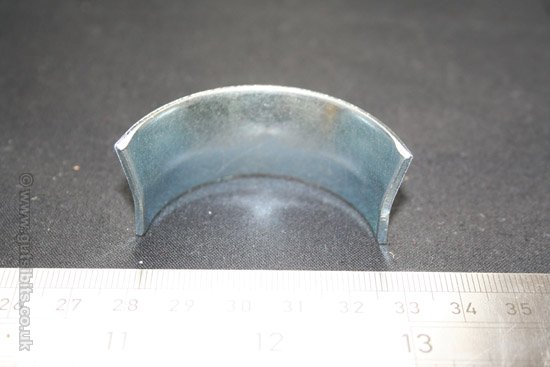
The two top corners cause the trouble, tend to be flared out a bit too far and have 'flashing' on the edges. Filing down a bit seems to be the answer.
Posted: 22 Jun 2013 at 19:30
Another slightly curious thing, which I think qualifies for inclusion in the 'faffing about' category...
When mounting the RH silencer it seemed to be fouling under the front of the footrest carrier such that it was a struggle to get the bracket to reach the bolt hole at the back (of the same bit of metal).
LH went on OK so go to check. Hmm the carriers ARE at slightly different angles (I'd noticed this before ~ there is vertical play in the bolt holes obviously).
Turns out to get the silencers to fit absolutely, loosen the two big rear Allen bolts that hold the carrier onto the frame (and also the frame together at the back), with the silencer on it pulls the footrest into line, the front up as far as it will go and the back down as far as it will go, silencer then suddenly fits exactly right, go figure.....
Posted: 23 Jun 2013 at 15:03
Ice cream tubs are excellent for temporarily storing and organising bits you take off the bike ...

This one has all the 'discards', mostly the fasteners that were replaced with stainless ...

Posted: 26 Jun 2013 at 18:12
"Good morning Mr. Phelps. Your mission, should you decide to accept it, is to make this lot ..."

"... fit into here ..."

Posted: 26 Jun 2013 at 18:43
By 3:30 pm still only got this far ~


Which is basically just connecting up the handlebar switches. No particular reason for the hold-up, was just a barsteward to do. New RH plug was wired slightly different relative to the loom socket, so had to move a wire. For the LH side, a mistake on both my circuit diagram and colours list (that says which Superdream h/bar switch colour goes to which Moto Guzzi loom colour) gave two Superdream light-blues, but I only gots one light-blue and the other is a black-green.
 Bugger...
I am searching for the old front-end wiring diagram with the colours info on it. Can't find it. 'Course I can't, I burnt it because it was obsolete...
After lunch, out with the Fluke multimeter and trace where these two wires go. OK it turns out black-green is input to dip-switch so connects to blue (from my headlamp enable relay).
The real light-blue is from indicator switch, so goes to pink.

I got the ache with it after that so that's where it ended for today. However that part seems to be all done now, assuming wiring is correct ~ I was originally going to either replace the Superdream wires or at least solder in extensions, but couldn't be asked in the end and simply made extensions to connect to the existing Superdream plug-blocks as before. I say 'simply', still quite a pair of wiring bundles to make though.
Also my stainless banjo bolts arrived in the post.
Posted: 26 Jun 2013 at 18:47
PS: the grey box between the frame tubes is the ignition amplifier. This is practically wired in as well.
Posted: 27 Jun 2013 at 18:22
Main loom on today! Pix ~


And that is that. Only the Sprint loom left to sort out then I feel a test coming on. Laters .....
Posted: 27 Jun 2013 at 19:53
Notes ~ (just thinking aloud, to crystallize me ideas, like)
The angled plate behind the steering head to mount the multi-way blocks is missing. I presume this is to stop them jigging about and rubbing against the tank or something. These connectors aren't particularly loose but it's something to keep an eye on.
However without the plate there's more room to manoeuvre and you can more easily get right up between the gusset plates behind the steering head to stuff wiring into.
There are 3 main earth points ~ the instrument console, handlebar (horn button) and ignition amplifier earth to the frame via a M6 bolt behind the steering head.
Tail light and regulator earth to frame via the (M6) hexagon pillar for LH sidepanel.
The main one exploits one of the rectifier mounting screws which doubles as its negative connection, hitherto this had a dodgy short wire to the bolt for the nearest battery side rubber, which necessarily isn't tight otherwise the rubber would be crushed! The rectifier may or may not earth to frame though its own support bracketry, in case it doesn't, or as well as, there is now a thick wire (in same gauge as for rectifier+ to battery positive) from this screw to battery negative. Thence the starter cable connects battery negative to back of gearbox and therefore, frame. Sharing the rectifier screw are the earth tags for flasher unit, power jack and leccy petrol tap.
Posted: Today at 19:33
Connecting up the fairing sub-loom! Actually was just starting this yesterday then rain stopped play.
Can't believe this and a few other odd bits took all day, also can't believe the rewiring is practically finished now! Don't know what to do with meself now ..
Sequence ~


... sorting out the yellow wire extension ...

