Calculating The Voltage Gain For A Valve

How To Calculate The Theoretical Voltage Gain Of A Small Signal Amplifier Stage

Last Modified: 5 Jun 2012
I
once had a big book full of little BASIC programs for calculating various simple electronic circuits. These were transistor circuits of course, and the calculations were fairly straightforward; all you really needed to provide was the Hfe (current gain) of the device and the program worked out the Log of the Vbe base emitter voltage drop for a particular input current, which of course is logarithmic, and which was also needed to get an accurate idea of how the AC input current behaved. Then it was simply a case of applying the amplified collector current across the load resistor. Very useful for telling you the steady state DC voltages of a circuit biased by your chosen resistor values (or not!) as well the AC performance.
Unfortunately it is not so simple for a thermionic valve. Its actual voltage gain in a circuit can be varied by a number of different factors, including Va, which is the actual voltage drop across the valve; Ia, the anode current, and for pentodes even the screen voltage, since this also affects anode current. Also, when trying to find data sheets for a particular type, the supplied information is either extremely sparse, so you still can't do the calculations, or else quite the opposite, where you are overwhelmed with copious amounts of meaningless graphs, labelled with esoteric nomenclature such as µ, gm, Ri, S etc., and so might just as well make as much sense as wallpaper patterns!
This is a shame because the graphs are trying to tell you valuable information. The best place to begin is ignore the endless variations and concentrate on simple basic assumptions, such as, that the Va is say 100V (usually a working minimum), so just use the Va = 100V graph. We are of course talking about conventional common cathode voltage amplifiers here, nothing exotic.
Given the graphs – these were taken from Mullard data sheets, done in their own inimitable style – all you need to know are µ, the amplification factor (or gm – see about pentodes near end of this page), and Ri, the internal anode resistance.
The Equation:


Or:

It's a simple equation and easily done on the most modest calculator.
- µ (mu)
- The amplification factor. The ratio of the change in anode voltage to a change in grid voltage in the opposite direction, under the condition that anode current remains the same. (E.g. if the anode is made 1V more positive, and the grid must be made 0.1V more negative to hold the anode current the same, then µ = 1 / 0.1, or 10.) Even the sparsest information usually lists the µ value, but be aware that the value can change somewhat with other parameters, so it should be accompanied by specific values for Va and Ia. That is, the stated µ is achieved with these other values being true. If the valve is a high gain triode like e.g. ECC83, then the µ doesn't usually change greatly, which makes it easier. If it's a low gain triode like ECC82 etc., then it can vary more so with changes in Va and Ia, so check it with the graph for the particular value of anode current you want to operate.
- RL
- The anode load impedance. This is not merely the anode load resistor value. If the anode resistor is 100k and the input to the next stage has a 1M grid bias resistor, then the AC load to the anode is actually 100k shunted by 1M, or 90.91k.
- Ri
- The internal anode resistance. This is more so dependent on anode current, which seems reasonable, so you'll need the graph plotting Ri over a range of different anode currents. Also known as Plate Resistance.
Triodes
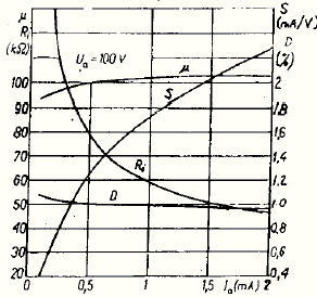
 ECC83 Graph shown at right is for ECC83 with Va = 100V. Note the µ line near the top is nearly flat overall and doesn't deviate much from 100.
The Ri is the dog-legged line from top left to bottom right. If we were to run the ECC83 at 0.5 mA, then Ri = 80 kilohms and µ = 100.
Therefore with Va = 100V, Ia = 0.5 mA, Ri = 80 kilohms and µ = 100, anode resistor (RL) = 100k, and assume (shouldn't really) that following stage's grid resistor doesn't have any affect. Try the calculation:
100k / (80k + 100k)Notice I knocked the 3 trailing zeros off all the resistances, assuming all the resistance values are in kilohms. Works provided you remember to do it for all including Ri! The answer is a voltage gain of 55.56 times (say X55) and is exactly what you get if you build the circuit.
x 100
I read recently on another web page, someone said "valves work better at higher currents". What this means is that increasing Ia has the effect of reducing Ri, as the graph shows.
What's the result? Let's try it and see – if Ia = 2 mA, making Ri = 50k, RL remains 100k. Do the sums:
100k / (50k + 100k) x 100gives us X66.6. So yes, just raising the Ia by 1.5 mA gives us an extra 20%! All we did was alter the bias (note: transistors can't do this – actually, Hfe decreases as the collector current increases). Actually it's a bit better than that because µ is slightly over 100 at this end of the scale. However there's a limit to how far you can go with this, and it's HT. At 2 mA there's a 200V drop across the anode resistor, and with the valve anode already at 100V, that requires a 300V supply.
6SL7GT My RCA manual describes the 6SL7 as a high-mu twin triode and gives µ = 70 and (Plate Resistance) Ri = 44 kilohms. This is on the basis that Plate Voltage (Va) = 250V and Ia = 2.3 mA (grid bias = –2V to set this DC condition). It's not accurate (Va wouldn't normally be that high in use), but to get an idea of what it should do with a 100k anode resistor:
100k / (44k + 100k)gives X48.61, slightly under that of ECC83, but then µ is lower. Not shabby though!
x 70
 ECC82 Some while ago I wanted a simple amplifier with a gain of just X10, and I used an ECC82 with a 47k anode resistor. This gave just over X10. With hindsight, as it were, I can now do the calculation to see if the theory matches experience.
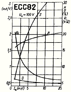
The Ia wasn't much, say 2.5 mA. According to the graph at right, this gives Ri = 12.5k, and µ near the bottom end at say 17. If Ra (RL) = 47k, Va = 100V (or thereabouts), then:
47k / (12.5k + 47k)The answer is X13.43, which is exactly what I got, if I remember correctly. Of course the ECC82 is a higher current valve, comparatively speaking, and the ideal working conditions are around the 10 mA region. Here µ is maximum at 19, while Ri is right down to about 6 or 7. 10 mA through 47 kilohms is a bit excessive though, dropping 470V, so let's try 22k:
x 17
22k / (7k + 22k)gives X14.41. Not much more, but better than an ECC83 could manage into just 22k.
x 19
If you run the ECC82 right at the bottom with Ia = 2 mA and RL = 100k, the situation doesn't change much, giving a gain of 13.33. Quite often the ECC82 is used like this as the input stage for a guitar amp, where the low gain allows a large input signal before overload occurs.
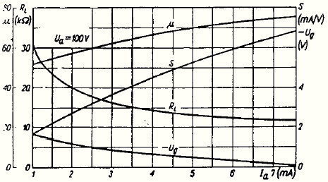
6SN7GT Medium-mu twin triode. In the conditions where Va = 250V, Ia = 9 mA, Vg = –8V, µ = 20 and Ri = 7.7 kilohms, RL = 22k, we get X14.81. So it's true the 6SN7 is much like ECC82, and you could pretty much use the above graph to derive gain from other operating conditions. You might ask why it is such a favourite of the Williamson amplifier design and suchlike, except of course that such a low-mu valve has appreciable built-in negative feedback (see article 'Inherent Feedback In Triodes'). Note that the 6J5 screened single triode is exactly the same as half a 6SN7.
 ECC81 This is sort of in between – if you run it at 2 mA with 100k load, the gain is X41.43, if at 3.5 mA and 47k, X22.74. This is actually quite flexible, you can juggle around with various values to get the gain you want.
Pentodes
The pentode is a quite different pail of whelks, although the equation can be equally applied. It's just the numbers are different. Many people slag off pentodes, but it's less realised now than used to be the case that the pentode has enormous amplifying potential. It originally started out as a means of making what was a triode amplify radio signals efficiently, achieved by adding the screen grid to block the inherent negative feedback field effect, and also the anode-to-grid capacitance, known as the 'Miller effect'. There followed problems with secondary emission from the anode to screen (meaning electrons literally knocked off the anode by 'bombardment' from the incoming cathode electron stream are 'sucked up' by the screen grid when it becomes more positive than the anode. This causes the anode voltage to rise again when in fact it should carry on falling). This quickly gave rise to the intervening screen grid to prevent this.
This worked fine as far as radio was concerned, but with a bonus (almost by accident?). Where a triode is basically a voltage controlled resistance, the pentode, on the other hand, functions like a current source.
EF36, EF37, EF86, 6SJ7 What this means is that the Ri, which is the same for all these types, is a whopping 2.5 Megohms (and often is listed as such in data sheets. Not too sure about 6SJ7, which may be a lower gain equivalent of the older EF6). The µ is similarly large – I have a copy of a Wireless World article, originally published August 1947, where the author expects the µ of his EF36 to theoretically be 4,500. In practice it wasn't as much as that, as his final gain figures showed.
It isn't either for two EF37A's I've got – with RL = 200k and screen grid resistors of 680k, one has a gain of X130, the other X140. Taking as an average 133, I worked the equation backwards to find the µ, and it turned out to be 1,800, or slightly over.
Actually that's wrong, because I forgot to add the 1 Megohms input impedance of the oscilloscope! This makes RL = 166.67k, so actually the µ is more like 2200, and the 'scope trace showed a lower output due to the loading, than there would be without. Without it, the gain is actually nearly X163!
Mind you these are 'good ones', so I should think that you could expect 1,800 as the average.
If I take this as the value for the lowest gain EF36 I have, the sum works out as:
200k / (2.5M + 166.67k)gives X111, and in reality it was about that with the 'scope connected. Without it should be X133. You should expect any EF86 to be similar. It raises the question what if you could raise the anode load resistance even further, making it more comparable with the Ri, because of course even 200k is a pityful fraction of it, and gives rise to the idea, which has actually been implemented, of the so-called 'starved anode' amplifier, where the anode resistor is 1 Megohms. The answer is a gain of X514!
x 1800
1 Megohms anode resistors are a bit impractical, and which again makes the Ia too low, so another idea, which was the subject of the above mentioned Wireless World article, is to use a cathode follower to multiply RL, the AC load as seen by the anode, but keeping Ra, the anode resistor DC resistance that provides the steady-state Ia, to a conventional value, thereby keeping a reasonable value for Ia. See the other article about 'High Gain Phase Splitter' for details.
gm or, "what, no µ?". Pentodes rarely have a quoted µ, instead it's most likely gm (can also be specified for triodes). gm is transconductance, more properly, signal grid–anode transconductance, and encapsulates in one term the quotient of the amplification factor divided by plate resistance (Ri). This is defined as being a small change in anode current divided by the small change in grid voltage that is producing it, with the condition that all other voltages remain the same. I.e. varying Ia, constant Va, and complimentary to how µ is derived (varying Va, constant Ia).
E.g. if a grid change of 0.5 volt causes an anode current change of 1 mA (0.001A), and all other voltages remain constant, then the transconductance is 0.001 / 0.5, or 0.002 'mho'. 'mho' is 'ohm' written backwards and used as the unit of conductance. Confused? You will be... it seemed more convenient(?) to express these values in micro-mhos (µmho). Hence, this would be written as 2000 µmhos (0.001 / 0.5 x 1000000). Just to complete the confusion, it may also be written, especially in one of those little Mullard data books, in its 'unconverted' form as '2mA/V'.
In the absence of µ, gm can be used instead to get gain:
The Equation:


This implies that gm is in µmhos. Let's try it with ECC83, which has a gm of '1.25 mA/V' for Va = 100V. That's 1.25 mA per volt, x 1,000,000 = 1250 µmhos. Do the calculation for RL = 100k and the answer is 55.56, exactly the same as from the 'µ' calculation version. How about that!
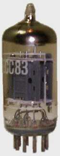
6AC7 is a metal screened 'sharp-cutoff' pentode that looks identical to a 6J5 (see photo at top left of this page). The RCA book quotes Ri as 1 Megohms and µmhos as 9,000. However it's a high current type so this goes with Va = 300, screen grid = 150V, and Ia = 10 mA. A practicable anode resistor value for these conditions might be 10k. Do the sums and the answer is X89.11. At much lesser Va and Ia, it may not change much. I don't have graphs for this so I can't double-check.
ECF83 is actually a radio valve, where the pentode section is used as a first IF amplifier/mixer. This gives it some odd characteristics, so to make it work satisfactorily as an audio stage the screen voltage must be kept down to <=50V – if necessary, use a resistor divider to hold it there. (It should be decoupled to 0V of course.) Otherwise the Ia is so large as to be practically unusable with a resistive load (the device is designed to use an IF transformer as its load). I couldn't find a specific value for gm, so had to extract it from an anode current vs grid voltage graph, for which Vg2 (screen) is 50V. If Ia = 2 mA and Va = 120V, you get about 1.3 mA/V, or 1300 µmhos. Ri is given as 600k, so there's a chance of working it out:
(1300 x 600k x 100k) / (1000000 x (600k + 100k))produces X111.43. For the triode section – intended for use as a local oscillator – according to its graph, if Va = 120V and Ia = 4 mA, it makes Ri = 5k and µ = about 9.5. With RL = 100k the gain is a feeble X9.05, which is why it's most often used as the unity-gain phase splitter following the pentode in an audio power amplifer.
ECF82 is a 'wilder' version of the ECF83 – in this case the screen voltage is 110V, and with Va = 100V, gm = 3 mA/V – again taken from a Va / Vg1 graph for Vg2 = 110 – or 3000 µmhos. For Ia = 2 mA and RL = 47k, gain = X126.17. At 4 mA gm goes up to 4000 µmhos making for X168.23 (more anode current is better, remember?). I have maligned this valve in the past but it turns out to be a better performer than ECF83. The triode, however, is useless as a voltage amplifier and is best kept to cathode follower and phase splitter functions.
ECF80 seems to have a similar gm to ECF82 – it being an earlier, lower current version of same – with the added advantage that screen current is less than half that of the '82. Like ECF83, screen voltage must be kept low, and one idea I've seen is to feed it through a 560k resistor from the cathode of the following phase splitter triode, whose grid is directly connected to the anode of the pentode, which makes sure that this voltage can never exceed Va. I.e. connecting the resistor to the supply is too much! Of course the actual screen connection is decoupled to ground through a capacitor.
This is one example of how making these radio valves work for audio does produce some slightly odd-looking circuit configurations. You have to bear in mind that for all the ECF80-83 types, the screen current wants to be quite high at about the same as the Ia, so the screen grid resistors must be chosen accordingly. Generally large-ish values will 'starve' the screen and keep the voltage down for best results. In addition, the triode must have a grid stopper resistor added as close as possible to the valveholder pin if you want to make sure it doesn't spontaneously leap into oscillation and transmit a UHF 'jamming signal' all over the place!
Analysis Of A Real Circuit
You could now examine a real circuit and find out whether the values were found mathematically using this sort of process, or whether someone just played around with some resistor values until they got something that worked. Take for instance the first ECF83 / EL84 push-pull power amplifier in 'EL84 Power Amps'. Assuming for the sake of argument that the supply voltage for the whole ECF83 stage is 250, and the screen grid is fed through 1 Megohms, limiting it to 220 µA and assuming this holds it down to 30V, which is good. Ra (the anode resistor value) is 220k, which to work means Ia must be 700 µA to maintain a usable Va of about 100V across the valve. Locating this on the Ia / Vg1 graph on the ECF83 data sheet for Vg2 = 30V, I deduced a value of maybe 0.6 mA/V, or 600 µmhos. Doing the calculation produced X96.59. Reducing the Ra to 100k, however, means Ia can now be increased to 1.5 mA, while keeping Va at 100. This then gives gm somewhere near 1.3mA/V or 1300 µmhos, and the result from these values is then X111.43, not coincidentally the same as we got before for the ECF83 (see above), and this with a lower RL of 100k. How many times does it need repeating – more Ia means more gain! How would this benefit the circuit as a whole? Because it provides more open-loop gain, which means that after negative feedback is applied (closed loop), the frequency response is flatter and the distortion is lower. Note R5 will need altering to re-establish the correct 100V drop across the pentode and 150V across the 100k anode resistor, or near as can be managed. On the same graph Vg1 (signal grid) = –1.5V if Va = 100V and Ia = 1.5 mA, so I make it 1 kilohms instead of 2.2k.
Notes
The reason why I only used examples of the 100V graphs above is because the gain you will get from these is usually a minimum. Increasing the Va, by simply increasing the supply voltage to the anode resistor, and all component values remaining the same, has the effect of also increasing Ia and hence µ, so the gain will be more. So if you calculate for a gain at Va = 100, you can treat this as a minimum since you should get more for Va = 150 – 200.
Appendix
I wondered if it were possible to do this for a power valve. As a simple example, a single-ended triode type, using Svetlana 300B. To cross-check the result, I first need to know what the AC anode voltage would be across a 5,000Ω transformer primary for a particular power output. This is found by multiplying the power by the load impedance, then the square root of that is the voltage. You can do this for loudspeakers, but just as well for the primary winding of an output transformer. I shall call the AC volts Ep:
Using either of the calculators below, the answer is 3.38. Dividing 223 by this gives 65V. I know this is right because the preceding amplifier stage, having a gain of X163, has an input sensitivity of 400 mV to achieve full output (10W).
__________________is 223Vac (r.m.s.). How much grid drive voltage will the 300B require to achieve this? From the data sheet: µ = 3.85, gm = 5500, and Ri = 700Ω .
Ep = √ 10W x 5,000Ω
Using either of the calculators below, the answer is 3.38. Dividing 223 by this gives 65V. I know this is right because the preceding amplifier stage, having a gain of X163, has an input sensitivity of 400 mV to achieve full output (10W).
Save This Page And Keep A Gain Calculator
The following is a tool for working out voltage gain given the criteria discussed, using the equation. You can enter impedance values as all figures e.g. '1000', or as e.g. '100k', '1.5M', '4.7k' etc. though don't forget µ is normally figures only. For the second calculator, gm should be written as µmhos.
Use this for finding the RL of the anode resistor in parallel with the AC input impedance of the following stage. Using this will give you a more accurate gain figure of what to expect in a real circuit.
