Germanium Power Amplifier – hybrid silicon BJT, MOSFET and germanium BJT
Last Modified: 20 Apr 2013

Compiled from a topic on the Audio Talk forum
M
y germaniums have arrived!

The complete collection:
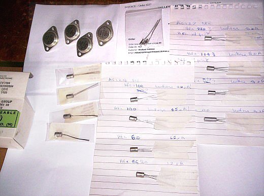
The CV7084 is the military version of Mullard OC35 ~ only £5.00 each from Langrex:


Even get a mica insulator kit in the box.
Background Info
This project took me two years to get together, mainly because I couldn't make up my mind how to do it. Originally I was going to repeat the kind of thing I tried building back in the 1970's, but with the hindsight of increased wisdom through experience. This included the idea that all the transistors should be germanium, I had a few as a starting basis, but extra were needed.
Having done that it then developed into an idea for trying out a transformer phase-splitter, like some of the earliest 1960's designs used to use. This would be the first time I'd ever tried this. (No such transformers being readily available before.) It then transpired that the small signal germaniums I'd got were inadequate to make the transformer driver (having poor gain and low Voltage) hence the design evolved into a power MOSFET driver with silicon bipolar input stage.
Also it was originally meant to be an integrated amplifier, incorporating vinyl EQ pre-amplifier and tone controls. However the space needed for the phase-splitter transformers scuppered that idea, similarly, it wasn't going to fit into the small wooden sleeve case that I had ear-marked for it either. It ended up in a 16 x 12 inch ally case and even that is just large enough.
So we'll "cut to the chase" and pick up the story at the commencement of some actual construction!
Beginnings
Thu Sep 23, 2010
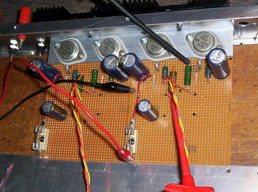
While I was still in the mood for messing about with boards I thought I'd run this up.
The power germs ensconsed into their final resting places.
It's a bit bigger than I thought it was going to be!

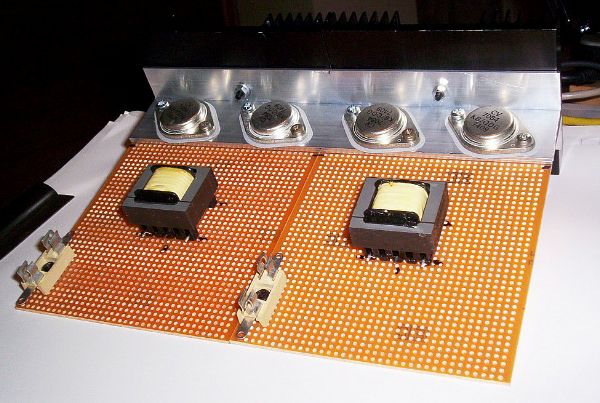
Notes
The transformers shown above are not the final ones.
Fri Sep 24, 2010
Earlier today spent about another £60 on Panasonic elecs and CC resistors for this, it's getting pricey for something that was originally just going to be a box of bits back-burner project to fiddle about with when I can't find anything better to do

It better work after all this, is all!
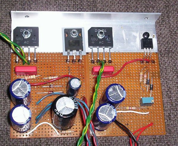
Mon Sep 27, 2010
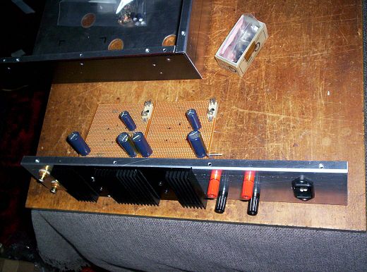
A quick fit-up of parts to see how things lie – actually wasn't that quick, did take a wee while!

Notes
Again the components layout is not final in this picture.
Alarms & Deviations
Tue Dec 28, 2010
I came across an unexpected problem, all this time (or mostly) I have been simulating it in LTspiceIV (aka 'SwitcherCAD') with a 8Ω load attached.
Took it off to simulate setting up the output bias current (a procedure that begins with wanging a 330Ω resistor beteen supply and output) and found A. it's very unstable with no load; B. the gain is twice as much.
So the current schematic (not included here) is total cobblers, for one thing it's the CCS that makes it unstable. So it's back to the basic method, biasing the output transistors with simple resistors and thermistors.
Then finally (cos of "interruptions") got around to boosting the gain, the input has to be a double stage with two transistors. (In fact early circuits I've seen typically have two single transistor stages in cascade, as input and driver, so why I thought I could get away with just one transistor as the driver I don't know.)
Cock up #2. ~ the OC44 I thought I'd got and was going to use as the driver transistor, isn't, it's OC84. Then it turns out OC44 is only 40mW anyway so would've blown up in the driver position!
This is all academic now anyway as I've redone it using AC127/AC128. The OC84's have been moved to the tone control input pre-amp. (This is not final, see later!)
Thu Jun 23, 2011
The trouble with designing for germanium transistors is you're always coming up against a brick wall legended (in best spray-can graffiti style) "can't do it won't go high enough".
The basic problem is germanium transistors were / are crap.
Crap max. Voltage limit Vce (too low); crap current handling capacity Ic (too low); crap gain Hfe (too low); crap bandwidth Ft (too low); crap power handling Ptot (too low); crap junction temp (too low); crap leakage current (too high).


I'm going to have to resort to extreme measures, like, use something else.
Also it's doing my head in constantly trying to think in terms of positive earth, it's just an accident waiting to happen when the wretched thing will be connected to its supply polarity the wrong way round, and that's it goodnight Vienna, so stuff it it's all negative earth from now on.
Whinge #3 ~ the specially custom made driver transformers are way not big enough (in my opinion) and pretty sure the frequency response is not good enough either (not enough interleaved layers – actually, no interleaved layers!), so the complete design quickly gets too complicated in various efforts to compensate, so they need to be biggerer so can drive the o/p trannies direct. Which was always the way originally. When I say 'originally' I mean back in 1960-whenever it was....
Are We There Yet?
Mon Jul 11, 2011
I think I know how I'm going to do this now.
However with two larger transformers in the box it won't be "integrated" anymore, there'll barely be room in the wood sleeve case to shoehorn in the power amp and its PSU by themselves.

Couple of phono inputs, speakers out posts; volume potentiometers on the front and that's yer lot.
Tue Jul 12, 2011
RS bits came this morning so we could be within a couple of days or so of getting the germs fired up in anger in some fashion or another.
One of three things will happen ~
A. It will work.
B. It will work but be crap.
C. We release the magic smoke (it blows up).
Still some way off of getting the custom special transformers design #2 (hitherto a spec was submitted and an order was put in), so, at the mo can only concentrate on will they, won't they, bias up properly ...

Place your bets now......
Long Hiatus!
Thu Oct 18, 2012
Remember this? Actually been doing some work on this last couple of days:
First of all find a case of some sort ~ the original idea of using an old wood sleeve case I've got wasn't going to work, not big enough.
Metal bashing a-go-go:


Next, how to make the output stage work.
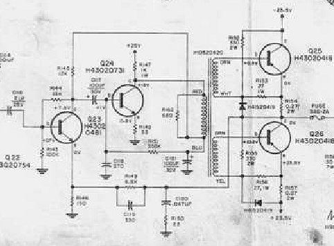
Example ~ this is the Burns Orbit 3 which somebody posted on WD forum I think. I think it's a guitar amp actually ~

Click for larger image
Note the DCR (DC resistance [of winding wire]) of the phase-splitter transformer secondaries are written, 2 Ω, fortunately for me!
This doesn't look like it will work very well, but nonetheless ~ for each half of the o/p stage, the secondary winding DCR forms a potential divider with a 220Ω bias resistor. The very low values chosen are because of the possible issues with collector-to-base leakage current you typically get with germaniums, which tend to knacker up any ideas about more 'normal looking' biasing set-ups; this method gets around any problems in this area by merely swamping it with 'brute force'.
I was umm-img and ah-ring about how to do this, and LTspice didn't help much as it doesn't seem to quite 'get' how germaniums work in reality, or not these ones anyway. (This was a problem with the germanium transistor models I was using, they had Vbe like for silicon ones, but I didn't yet know how to change this.)
Getting Somewhere
Typically, it turned out to be much, much simpler in practice.
I thought the 220Ω bias resistors a mite 'OTT' in terms of low value, so had opted for 470Ω.
And as it turns out, the transformers I've got have 3.5 DCR on the secondaries. More of that in a mo ~ anyhow, try wiring it up as per LTspice and testing it with real Volts and see what happens....

Thank the lord for current limited bench PSU's, it bottomed out big-time!
The LTspice model is telling fibs then.....
Ok so, I'd got biasing resistors in series with the secondaries to lift the bias Voltage (of 10Ω originally!), so kept reducing them until the PSU stopped limiting.
They ended up as 0.47Ω ~ plus DCR of 3.5, = 4 Ω, to get the transistors biased on and conducting lowly.
Going back to the Burns, and given that the bias resistors are increased to 470Ω, if you divide all these values these by 2 you roughly end up with the exact same values as the Burns uses. How about that?
+Vee @ 34 Volts ~

.... and here sez o/p stage is drawing 45 mA (but I think meter is under-reading slightly) [2nd scale from the top, 150 mA FSD] ....

This is the resistor bias chain plus the transistors, the resistor chain is 33 - 36 mA so the transistors are both passing 12 - 15 mA -ish.
The output DC point is ~

I left it idling a couple of hours and nothing changed, so looks like it might be a case of 'Arise, Sir Goer' (it's-a goer)
Thu Oct 18, 2012 (some time later)
Still working!

Close-up of the phase-splitter transformers, I had these made specially. 2 x 1.2k : 2 x 32Ω. They are well 'OTT' for the job, but originally I was going to use weedier little PCB mounting ones which I subsequently realised (by using something similar for something else) might not have a decent frequency response actually.

As was mentioned previously the front-end is cribbed directly from 'bonkers MOSFET amp' i.e. the phase-splitter transformer will be MOSFET driven.
Circuit ~

Click for larger image
Subject to change at a moment's notice of course.

Fri Oct 19, 2012
Finished populating the board ....
Possibly .....
If it works ......


Sat Oct 20, 2012
Power supply next ~ tested the mains side wiring last night, in the process discovered the indicator lamp I put in wasn't actually a neon, but a filament bulb, survived the mains for precisely a millisecond.
First need to update the schematic a bit, turns out the mains TX is 2 x 35V, + 10% overwind, not 30V as I thought.
Sun Oct 21, 2012
Big day today is testing the PSU board. (After groceries shopping, just got back.)
Came across a problem last night trying to finish it ~ the mains TX is 2 x 35VAC, OK that will work with reservoir caps of 50V....
No it won't, as it's 10% overwound so each winding is more like 39VAC off-load, which pushes the DC over 50V.
So had to scratch around a bit and resort to caps in series, means the reservoir values are half what I originally wanted.
I remember having this problem before with this transformer ~ originally an RS item bought over 20 years ago ~ but as each winding has a centre-tap (interestingly, as 15 - 0 - 15V), what I did then was make like two full-wave supplies and piggy-back one on top of the other.
It also meant the bridge rectifiers I was going to use had to be changed as well, as again 'only' 50V. Fortunately my supply of 600V ones are 4 Amps so should be OK.
Finally!
Sun Oct 21, 2012 (some time later)
It's making noises!!


Revised circuit diagram ~

Click for larger image
The power supply ~

Click for larger image
Sun Oct 21, 2012
Mods to amplifier schematic ~
First tested PSU with the bench supply, OK, then wired to transformer with o/p stage connected only, OK.
Then when I first fired it up with everything connected (i.e. plus input/driver) nothing caught fire, but not long probing with DMM I got that impression like you do that summink's a bit awry somewhere. Well you do if you've experienced RF oscillation in a valve amp, you get weird sort of DC readings. It was a bit like that.
Put DMM on AC onto speaker terminals, sure enough there was 2 - 3V of ~ something ~ coming out.
As it happens the Fluke has frequency counter function, so switched to that and ~ it's oscillating at 150 kHz! (-ish.) (It's interesting in itself that the Fluke can not only measure that sort of frequency, but the AC Voltage of it.)
Adding C7 stopped that. Obviously it's because bandwidth of the transformer doesn't go that high, so it doesn't get through to the o/p stage and so C6 can't do anything about it.
#2. The MOSFET current is a mite too high @ 40 - 45 mA whereas I preferred 30 - 35 mA. This is interesting 'cause bonkers MOSFET amp does that in the same set-up, but there you go, gate Voltage must be lower on these ones.
This was addressed by increasing R11 to 10k, and decreasing R8 to 4k.
As an aside, the DC difference across R14 is only about half a Volt, in case you were wondering.
Aside #2 ~ it may have escaped anyone else's notice that the open-loop gain on this is not great. This is deliberate so that the damping factor is on the low side, like a valve amp with little or no NFB (note also local feedback is applied between input and driver by R6, which increases the effect). It was proved in simulation anyway that it does have this sort of behaviour.
Despite the o/p coupling cap being 'only' 1,000 µF, the bass is all there, again much as though the damping factor is low. Like a valve amp.
Sun Oct 21, 2012 (some time later)
Still working! Got a Radio 2 jazz prog on at the mo.
Now the David Jacobs show. Very similar.
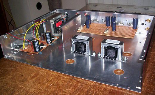
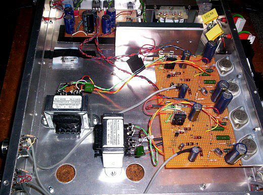
More photos ~
Power supply board ~

Finished amp ~ (sans lid)


Mon Oct 22, 2012 2:37 pm
Still working!
Modifications!
Modified diagram:

Click for larger image
Oh No Now What?
#1. Last night I was getting a bit of what a friend calls "transistor ear". The treble is quite 'hard' and agravating my tinitus.
Mind you it's wonderfully detailed, sort of like the music is put under a microscope so that nothing escapes. Janice Long played The Jam 'Down In The Tubestation At Midnight' and there is this subtle percussion effect going on on the right channel for the choruses, guess it's supposed to be like clickety-clack of wheels on rails, never knew that was in there before.
Later, Kate Bush 'Babooshka', I should know this quite well, there's a 'yelling' bit at one point in the background which I should already know exists but not heard it as clearly as this before, it was quite surprising.
Notwithstanding, it's still a bit overwhelming.....
#2. The bass roll-off is a bit excessive (reactance of C2), so there's a perceptible lack of 'body' at the bottom end of the midrange.
#3. Too much gain! Volume controls were only 10 - 15 degrees off the bottom so difficult to set (too close to 'off') and it was already a bit too loud.
To get around these R18 & C8 were added.
It sounds a bit 'warmer' now.
Mon Oct 22, 2012 9:02 pm
Forget everything I've just written about RF chokes, it's all cobblers. Must be something to do with FM .....
Addendum
There was nevertheless something going on that was not yet fully revealed, it didn't come to light unil November (see Nov 15th below) also while trying the amp with other speakers and sound sources in the same month. The experiment with the R.F. chokes was however trying to indicate that a problem existed.
Now onto CD's and everything's back to as previously, including tweeters wound up to normal ......

Tue Oct 23, 2012 2:12 pm
Just to double-check there isn't something odd going on with the FM tuner, this morning I got it going in parallel with the Troughline so I could compare, they're exactly the same so it's all to do with FM quality. Which as we know is heavily modified with compression / treble boost / normalization / noise gating et al ~ and which is what makes Classic FM sound so dreadful at times.
Having said that, Radio 2 seems less abrasive today so, as the amp has been working a couple of days now, maybe the caps have settled down or something ~ I try to avoid using expressions like 'burn in'
but could be something like that. Mind you doesn't help it being so sensitive, so I have resorted to adding a 100k resistor to each potentiometer to reduce the level, otherwise it's quite difficult setting and balancing a listening level so close to the bottom of the tracks. (The resistors are SMD thick film which 'I can't hear'
, just in case of altering anything.) Problee safe to say this is the best S.S. amp I've ever made, mind you haven't done anything like this for what must be over 30 years. Sure better than anything I could have turned out back then, ignorant as I was in them days


Tue Oct 23, 2012 2:26 pm
Just one remaining minor fly in the ointment ~ well a big one actually ~ the mains transformer BUZZES LIKE CRAZY
 ~ it's doing my head in.
 So I've been onto my transformer man for something more betterer in the concentric wound line, (original is split-bobbin ~ ZZZZZ
 ), first thing he reckons is the stack should half an inch thicker for a start.
The TO3 insulators are the rubbery 'greaseless' type (aka 'sil-pads'), even so I tend to add a dab of paste as well.
#2. The little finned heatsinks on the MOSFET's Were from eBay, but can't find them now, actually for TO220 size so I had to cut off the two side cheeks on the opposite side to the fins, as the MOSFET's are TO-247 package (bigger than TO-220).
Thu Oct 25, 2012 1:55 pm
Just for a conclusion, of sorts ~
Either I'm getting more used to it or it's settling down more, a couple of progs on Radio 2 yesterday evening sounded awesome. (Possibly engineered better than normal as well which would've helped a lot.)
On the World Design forum topic where the Burns Orbit schematic was originally posted (for my benefit), I got a distinct impression of 'lack of enthusiasm' about the basic concept .....

Meanwhile elsewhere, another forum topic that Google had thrown up had a mention, basically saying "OC35's should not be touched with a long pole" or words to that effect, well they seem to be doing alright to me!
(Moral: be careful with what you read on the Internet, there's an awful lot of bollox, interspersed with occasional but increasingly isolated islands of sanity.)
No, Still Not There Yet
Thu Oct 25, 2012 4:24 pm

Still on the trail of the bright treble, as an experiment I tried inserting 20 uH R.F. chokes (I just happened to have found) in series with the speaker 'live' terminals. That toned it down a bit! The tweeters are now restored to their 'normal' level (on 50Ω WW potentiometers), previously I had to turn them down! Still didn't help much....
I've tried this before on amps using global NFB, an RF choke on the output makes them much more stable. Maybe it doesn't like the speakers leads capacitance, or something like that. That's the usual reason.
The RF choke isolates the o/p point where the NFB is taken from, from the external load and gives it a better chance to feedback some actual HF.
20 uH is only 1 Ω @ 8 kHz, so as a pure reactance in series with a speaker that would be inaudible, but that isn't what I'm hearing, it's made a big difference. Much more mellow.
In a relative context I hasten to add, it's not really a 'mellow' amplifier but the treble is much more under control and consequently the midrange sound better as a result.
Fri Oct 26, 2012
Appendix update re the power supply ~ added a 1 µF suppressor cap with mains transient suppressor (varistor) in parallel across the mains switch, to stop the terrifying *POP* noise from the speakers when it's turned off. This is due to picking up and amplifying the back EMF pulse from the mains transformer. Also, things like clicks and pops if e.g. a light switch goes off elsewhere in the domicile, i.e. mains bourne noises.
Sun Oct 28, 2012
Updated diagram ~ some transformer pin numbering was wrong way round:
Click for larger image
Plus, transformer connection diagram ~

Mon Oct 29, 2012
Updated power supply ~
Click for larger image
Notes
It wasn't spelt out but the power supply has two parts, one for the input and driver stages and the other for the output stages. Both are regulated.
The input and driver PSU needs to be regulated else the dual parallel MOSFET and transformer circuits are unstable and oscillate at low frequency.
The output stages PSU is regulated because, as per the Burns Orbit design, the Voltage across the bias resistors for the output transistors must be held constant regardless of load, else there's a chance of crossover distortion if the supply Voltage 'sags'.
Tue Nov 13, 2012
Got the new mains transformer installed, much better than the original ~

It's All Starting To Make Sense Now
Thu Nov 15, 2012
Small panic-ette today, while I was swapping speaker leads between this and breadboard amp 'tother day I was wondering why disconnecting / connecting to this amp was making alarming crackling noises and mahoosive cone movements
Measure DC on speaker terminals with no loads connected there is –0.7 - 0.8V across them ~ negative ~ hmmm ..
Where the hell is that coming from ~ and how ..

Very odd.
On a hunch, switch DMM to AC, > 10V!

Nowt else for it, dust off the 'scope (does it still work?) and have a poke about.
SPLASH!!
All is revealed! Bleeding thing is oscillating, but OK while a low impedance load is connected. Very difficult to resolve what the frequency is as it's a right hash, but seems to have a fundamental 50 kHz -ish.
It's approximately a 15V peak square wave, 50 kHz plus all the other garbage mixed in, bluddy Nora no wonder the speakers are crackling!
A load damps it so it works OK, but not really ideal to rely on that.
47Ω resistors across the terminals works, but, messes up the sound by noticeably interfering with the speakers' dynamics, so that's no good.
Putting snubbers across the terminals (e.g., 10Ω in series with 100nF for example) just cleans up the square wave and lowers its frequency! Still coming out at 'full power' (nearly destroyed the 2W 10Ω in the test snubber in just 2 - 3 seconds).
I know what this is, as I've come across it before ~ if the o/p transistors have no load to speak of then the driver is also working into a higher impedance (negligible base currents, in this case), making it unstable. The transformer coupling is not ideal so it can't keep a lid on the HF acrobatics.
The solution (I hoped), is a snubber across the phase-splitter transformer primary, 1k and 10nF seems to work. This damps the ringing on the primary as well.
NB: it also turned out that this ringing started showing up as a bit of ripple on the sine wave when turned up > 10V peak.
The 10nF snubber caps started out as HV ceramic disc and then believe it or not I can hear the blasted things ("zzz - zzzz - zzz - zzz" which should instead be "sss - sss -sss")
Swapped them for 10nF 160V polystyrene, sorted.
Wed Nov 21, 2012
The saga continues!
Been fiddling with this most of today.
At the Owston meet we had put it on Andrew's PC 'scope test facility, which revealed some odd behaviour. Well I kind of suspected.....
OK so first prob, the HF instability. Started by disconnecting all the small value caps (get back to basics) ~ on Saturday afternoon (at Owston) I remembered an earlier version LTspice simulation of this many moons ago, where a cap between MOSFET drain and the NFB point at the first transistor emitter (across what is now 100k resistor R6) could cause it to oscillate, but that was without an 8Ω load connected. (Instead, 470Ω.)
All the subsequent simulations were ~ yes, with 8Ω load connected!

Conclusion ~ MUST NOT strap a cap across the 100k resistor. (R6. This is the local NFB for the front-end.)
Playing with sig gen and 'scope proved that ANY caps applied to anywhere to reduce bandwidth of the front-end is a no-no , this exacerbates the problem ~ the problem being, it really needs to make the transformer work at HF, so every attempt to reduce its bandwidth just increases the ringing on the transformer, i.e. it's 'losing control'.
The resonant freq of the transformer is the peak we saw on the response on Andrew's screen, about 50 - 60 kHz.
After the peak, output runs to zero at about 100 kHz.
The resonance peak can be killed off by a rather aggressive Zobel across the primary, it ended up as 220nF and 470Ω.
As the o/p impedance of an amplifier rises with frequency, and proved on the scope, this can make it unstable if load is disconnected, so I then experimented with Zobels across the o/p terminals until both channels continued to show a flat line AND take an input signal with the load resistors disconnected. Result.
This just leaves the one NFB cap, C6.
The hum pick-up issue is most prominent on left channel ~ can't remember which one we tested ~ this is quite likely as this phase-splitter transformer is closest to the mains transformer.
RH channel shows about 1mV peak of hum ('scope goes down to 2mV/cm, [with x2 control]), LH channel is a smidgeon over 2mV.
I had an idea
 move the phase-splitter transformer. Undid it's nuts and moved it further away. Found a place nearer the front where the hum on both channels is the same, 1mV. That'll do, drill 2 holes there, proper job. I can live with 1mV peak of hum rather than remove and relocate the mains TX externally.
 Plug it together for a listening test, OK, but it had lost its sparkle. So the phase-splitter transformer Zobel caps were reduced to 47nF to get it back. This means it may still be prone to be unstable if loads disconnected, but so be it.
At Last
Schematic link ~ FINAL!

Click for larger image
PS: L4 merely represents the twisted wire pair connecting board to o/p terminals. Note also Zobel snubbers across the output terminals.
Thu Nov 22, 2012
Just a note ~ it's probably more like a valve amp in terms of open loop gain is low, so damping is low, and output Voltage is variable with impedance. Which is what I wanted, in case anyone was wondering
Thu Nov 29, 2012
Changed over to the Tocos Cosmos volume potentiometer (Japanese dual carbon track). Originals were the Rapid 24mm carbon singles, which are not too bad really.
Finally got in a proper listening sesh after tea 'til about 1 am.
After the 6V6 amp, tweeters had to be reconnected and restored to 'full power'. Means, what they had always been originally set at for months/years.
This might imply the Cosmos is 'mellow', it isn't, an apt description might be 'full-bodied'. As the reviews said bass is all there, BUT, interestingly, is still quite tight, i.e. markedly 'non-flabby'. Even the deep heavy stuff. Which was a surprise.
The treble is not 'in yer face', but nevertheless all in there. No missing bits.
This amplifier is turning into a benchmark against which anything else I build must be compared.

Played a varied bunch of stuff (in the time available), and all was ecstasy. I was on cloud nine, I was.

Chuck anything at it, it plays sublimely.
As two units in the chain now have Cosmos potentiometers (the other being the Input Selector & Line Pre-Amp), the trick here is have one or the other wacked up to full, so it's near as possible working as just like 100k 'earth leak' resistors in parallel across the signal path, and use the other one as the volume control. Best results for the germ amp seems to be, have its own control full up so that the board input is more or less directly coupled to the selector box op-amp buffer, and the selector's Cosmos is then the volume control. Barely much discernible difference 'tother way round though.
I is happy bunny
Sat Dec 01, 2012
One more piccy I've just found in the camera ~ moved phase-splitter transformer plus few comp changes on board. Plus Zobels on the o/p terminals in the background.
Tue Dec 18, 2012
Acting on a comment from somebody else, I found a schematic for the Harmon Kardon SR900:
The way the driver is configured is same as an earlier version I was working on ~ where the phase-splitter transformer is not gapped (my first version small ones [yellow in the pix] weren't) ergo it is driven 'parafeed' (parallel-feed) from the driver transistor collector, which has a 1k collector resistor, and the other end of the primary is AC grounded through 100 µF. The bias for this same transistor is then taken from that same point (100 µF cap), which of course equates to the no-signal collector Voltage of the transistor. In this way the transistor regulates its own base bias by adjusting the collector Voltage to suit, and was, if not still is, a common technique.
Don't know how this amplifier compares to the vintage designs sound quality-wise, as it has got modern passive components, as are the phase-splitter transformers of modern materials and construction, but, after making new loudspeaker leads from solid-core CAT 6 network cable, and putting impedance correction networks on the speakers, and with good quality volume potentiometers on the input (Tocos Cosmos), it sounds pretty clean to me!
Conclusion
The amplifier has been in daily use ever since and has so far performed faultlessly. It is also used for video soundtrack as well as FM radio, CD etc. The speaker damping is not large, much like a valve amplifier, so the clincher has been getting the speakers' impedance correction networks right, and the use of Cat 6 network cable UTP solid-core for the loudspeaker leads. After some months of constant use the amount of detail that is often revealed in some music, even FM, still surprises. The overall tone, however, is perfectly even and natural sounding with no fatigue.
Two metres each of Category 6 network cable is used for speaker leads ~

This is wired as: two pairs for live (red), other two pairs for return (black).
The twist of each pair has a different pitch, so as this might affect the length of the wires, I used the two shortest pitch red/white and brown/white pairs for live, and the longest pitch green/white and blue/white pairs for return. I terminated them with gold plated 4mm ('banana') plugs, as from e.g. Maplin or Rapid, the screw type ones; with these the four twisted solid cores easily fit into the cable entry space and clamped by the screw.
This is the way to do it. Staggeringly better than most of the common multi-strand thick speaker cables e.g. Maplin Shark, which is what I had been using hitherto, and for some time.
One of the test CD's was Coldplay A Rush Of Blood To The Head, very nicely made but, to me it always had some annoyingly mushy indistinct aspects to some pieces. Turns out this is entirely due to some rather overly enthusiastic use of echo. I had never heard this album this pin-sharp before, so by that alone, deffo 'a result' !
Below is the current loudspeaker circuit, using the impedance correction network based on that made by the calculator on this web page: Speaker Impedance Correction For Valve Amplifier. I include it here because all this additional 'research and development' occurred at the same time as the germanium amplifier was finally being fettled, so it was all related.
"Let's assume you have a loudspeaker with 8 Ohm, having its maximum impedance of 16 Ohm at 1000 Hz. The impedance rise is of no importance when a conventional amplifier is being used." (Meaning, a solid state amplifier with very large damping factor.)
"However, if you connect this speaker to a valve amplifier, then this impedance rise leads to an excessive level at 1 kHz. Therefore, this impedance rise should be compensated for in the crossover.
"To achieve this a RLC element (pictured on own page) should be connected in parallel to the crossover." (That is to say, across the input terminals of the loudspeaker.)

Click for larger image
The plot of the above LTspice simulation schematic is:

Click for larger image