10W Push-Pull (EL84) Amplifiers
Last Modified: 5 Jun 2012
D
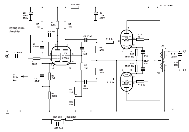
ue to popular demand I include here three push-pull class AB amplifiers using EL84 output valves. The first circuit in the PDF shows an archetypal, small to medium power push-pull amplifier configuration that uses a triode-pentode (ECF83) in the front-end. This configuration, in various forms, has a long history and, due to coupling the high gain of the pentode with negative feedback, provides good quality, low distortion reproduction for domestic use. This does not exclude it from musicians' applications and indeed the circuit was 'borrowed' from a book Build Your Own Valve Amplifiers for a design for guitarists. The triode section of V1 performs the phase splitting for push-pull, and the sensitivity of the EL84's is such that this can be delivered directly to the output valves without any further stages.
 Circuit #1

EL84 cathode resistors are 150Ω for about 48mA anode current giving near class AB1 type operation. These can be increased for nearer to class B, especially if 'sag' is desired (guitarists' terminology). Input sensitivity is >=500mV for 10W output. If HT is 300V, then up to 15W may be possible but quiescent anode current must not exceed 50mA, i.e. a maximum anode plate dissipation of 12W.
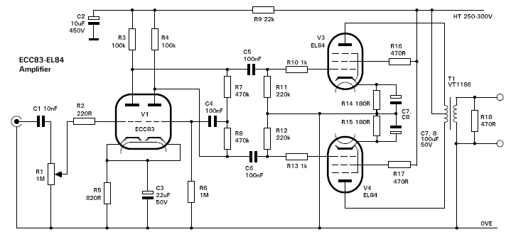
 Circuit #2
 The second circuit is borrowed from a Vox set-up and is of that other typical configuration, namely a double-triode front-end where the second half is driven as a unity gain inverter from the first half (this is called a para-phase splitter). Again the equal opposing signals thus produced drive the EL84's directly. There is no negative feedback here, so all the various nuances of the output transformer can be exploited. EL84 quiescent anode current is slightly reduced, but can be reduced more by further increasing the cathode resistors, and can be down to 20mA for more class B than A.

 Circuit #3
 This third version below is the 'GEC 912+', that uses two ECC83 triodes in the front end. Apparently this was produced to rival Mullard's 5-10 design.

A suitable power supply is shown below. For musician's use and to promote 'sag', the two output diodes may be replaced with a EZ80 or EZ81 rectifier valve, although you should also provide it with its own extra VT1036 heater transformer to avoid a large voltage difference between the cathode and heater (i.e. if connected to the existing, 0V centre-tapped heater supply). Also not shown is a standby switch which should be inserted between L1 and C2 if desired.

