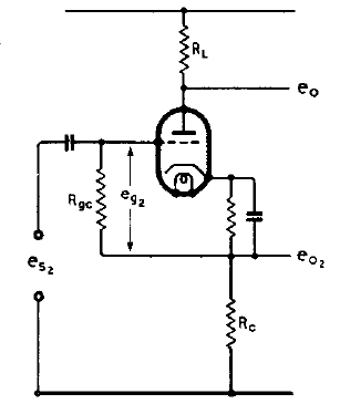
Input Impedance Of A Cathode-Follower Phase-Splitter

Last Modified: 5 Jun 2012
T
he above shows a cathode-follower type phase-splitter where the input impedance (Rin) is that of Rgc multiplied by >=10, by virtue of its other end being connected to the cathode. If the valve is a triode, and its µ is between 20 – 30, then the result of the impedance multiplying effect may be assumed to be Rgc x 10, since a cathode follower nearly always has a 'gain' of 0.9, that is, the output at the cathode is the input voltage – 10%.
Important this works ONLY if the cathode bias resistor is bypassed by a capacitor as shown above, so that the bottom end of Rgc is in fact AC coupled to the cathode. So if Rgc is 1 Megohms, it is safe to assume that Rin = 10 Megohms.
If you want to be more fussy than that, or if the valve is a pentode wired as a triode, then the actual ratio can vary depending on the individual characteristics of the valve employed. A formula used to find what the actual input impedance will be according to these characteristics is as follows:
Rin = ((Ri+(mu+2)*RL) / (Ri+(2*RL))) * Rgc
- Ri
- Plate resistance, or internal anode resistance of the valve, depending on the biased DC conditions*.
- µ (mu)
- Amplification factor of the valve, depending on the biased DC conditions*.
- RL
- Anode resistor value in Ohms.
- Rc
- Cathode resistor value in Ohms – assumed in equation to be the same as RL so not actually included.
- Rgc
- The grid bias resistor value in Ohms.
For example EF86 or EF36 wired as triode, Ri = 10k and mu = 28 (triode operation), RL = 20k (anode resistor), Rc = 20k (cathode resistor), and Rgc = 500k (grid bias resistor). The input impedance is 6.1 Megohms.
Try these in the calculator below:
ECC82, mu = 18, Ri = 9k (from Ia = 5 mA), RL and Rc = 47k, Rgc = 1M
6SN7, mu = 18, Ri = 10k (Ia = 5 mA), RL and Rc = 47k, Rgc = 1M
ECC83, mu = 100, Ri = 50k (Ia = 2 mA), RL and Rc = 47k, Rgc = 330k