Last Modified: 20 Oct 2012
Ambit FM Tuner and Stereo Decoder project

Compiled from forum topic
Fri Aug 27, 2010 9:33 pm
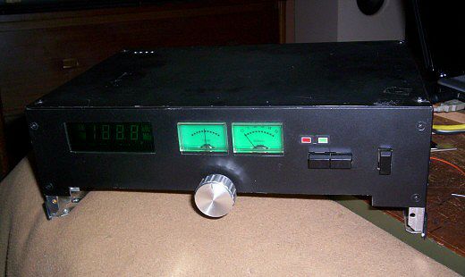
After tea tonight I went up in the attic and found this ~ it's the tuner I made out of Ambit modules way back in 1989, and it still works. Not too badly at all actually...
Ambit
Ambit International were a small company based in Brentwood Essex, starting I think as just two guys in a flat over a small shop in a side street, who sold quality FM tuner kits and modules, and for other functions. From about the mid 1980's I was collecting together enough modules to make a good FM tuner, it was finally assembled using custom cut panels to make a case in 1989. After getting swanky new shop premises at the back of Brentwood High Street, Ambit were finally taken over by Cirkit based at Broxbourne, Herts, and that's the last I heard of them.
I had come into the habit of using Internet radio streams, but to be honest the FM tuner sounds a lot better, much more rich and 'lively' and more involving to listen to.
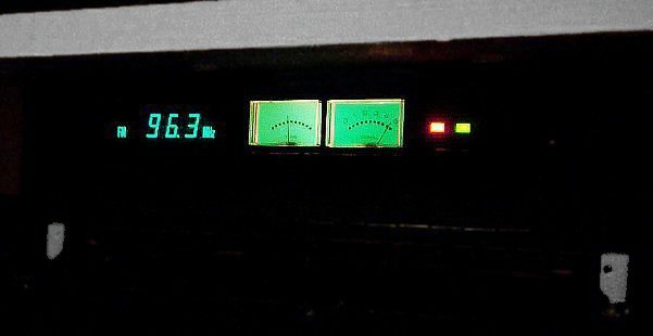
Note it's got a special VHF digital frequency meter for the freq. display, and the display is actually a glass gas discharge 'tube' which needs a little heater transformer to make the filaments work.
The original idea was to give it 12 preset buttons for stations, thought it was a good idea at the time but in practice is a bit of a pain to use sometimes.
The things you remember ~ I remember the signal threshold for the stereo switch is adjustable and I deliberately set it on the high side.
Can't remember what the green LED does but it's always on. There are no legends or labels!
Sat Aug 28, 2010 4:43 pm
OK so, the button under the red LED turns AFC on and off, and I've finally worked out from sketchy memory that the button under the green LED narrows the bandwidth if the audio is a bit noisy. Can't force it to work in mono though.
The green LED is just "power on" I think, which is a bit pointless as the rest of it lights up like a christmas tree anyway.
Finally got the dipole installed in the attic today, and got a VHF lead ready for the Leak TL3(s), or whichever can be made to work
Antenna
The FM aerial was made from two telescopic antennas, mounted in a ABS box, and further mounted onto an aluminium channel support screwed to a high joist in the attic, in vertical polarisation. Albeit FM is horizontal polarisation, having it vertical means it is omni-directional, i.e. can get transmissions from any direction. Obviously it is not very sensitive, however, it is delivered to the tuner via a Antiference mast-head distribution amplifier (4 outputs, plus the TV signal from the TV antenna) so actually it is quite sensitive enough. The telescopic aerials are easily adjusted for length for the correct half wavelength for FM (1 metre tip-to-tip).
NB: I was subsequently reminded (through observation) that the green LED indicates that the IF module is getting a good signal.
NB: I was subsequently reminded (through observation) that the green LED indicates that the IF module is getting a good signal.
Sat Sep 25, 2010 10:29 pm
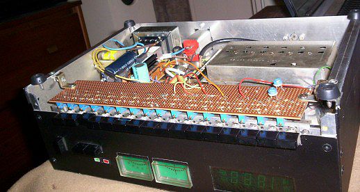
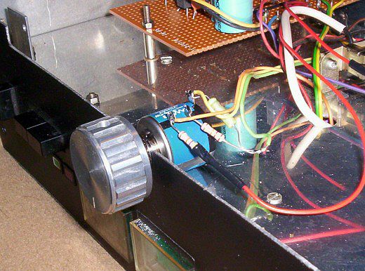
Just performed the long awaited mod on the Ambit tuner, this comprises of replacing the 16-fold latch button pre-selects (damned stupid idea!) with a single multi-turn tuning pot. (This is a 10-turn wirewound potentiometer from Rapid Electronics, 100 kΩ.)
The board below to be removed. This consists of 16 multi-turn presets each tuned to a particular station and selected with a latch button switch. Thought I was being quite clever but in reality it's quite a pain in the arse to use because there's no ready tunability so you're forever fiddling with whichever selected preset:
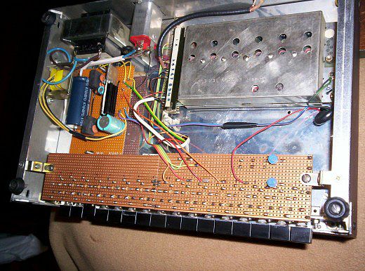
The above offers a good view of the Ambit tuner head module, this is a high gain device with no less than 6 tuned circuits ~ count 'em. It also has a buffered RF output for the DFM (Digital Frequency Meter display module).
The blue things underneath are the multi-turn presets, originally you dropped open a flap which was the bottom bit of the front panel to access the adjuster screws ~
Sat Sep 25, 2010 10:39 pm
The whole lot is replaced with this. A bit tricky as I had to figure out / remember what the different wire connections are for as I had lent all the literature about this thing to somebody and never got it back.
Below, inside view of the topside, the IF amplifier is on the right, stereo decoder top-left and DFM bottom-left. The tunerhead and power supply being in the bottom half (see above).

Sat Sep 25, 2010 10:51 pm
It's a lot better for it as well, for one thing it means can have a 1uF cap between wiper and ground like it's supposed to have if memory serves correctly. Used to have some weird effects before without it 'cause the AFC works by varying the Voltage on the plus end of the tuning pot.
Been listenig to it last couple of hours, never worked so well I'm pretty sure. With the top cover off I found the stereo threshold preset as well, so turned it right down, this means it's got to be an absolutely strong signal that will do stereo without any noise, anything less, mono. There is no manual override mono / stereo switch.
Project finishing / modding job No. 19
Fit new display filters, of considerably better matching neutral colour.
First up, the Philips DIY CD player. Still can't believe it took 3 and a half hours!!!!
I had to move the control/display board back a couple of mm so there'd be space for it, (it's thicker), this meant thickenning the back of the control buttons to reach. The display has yellow LED's and all previous attempts to find suitable filters just make it very dim. Not any more.
Second up for the same treatment, the Ambit FM tuner. Who the hell put this together anyway? LOL...
 I worked out everything gets an earth return through the chassis. I found this out as I wanted to add an earth lift resistor.
 The IF board and decoder are earthed direct through their ground planes via the mounting pillars. The tunerhead is earthed via the IF lead screen from the IF board (and hence through its mounting pillars); the DFM board is earthed from the tunerhead. Well that part of it's OK...
Drilled out the ground plane encroached mounting holes to 4mm so can add plastic insulator shoulder washers (actually from power transistor mounting kits and cut down). Next, add beefy (-ish) stranded earthing wire direct from PSU board (hitherto it went straight to chassis via the mains inlet filter earth terminal) to IF board, thence decoder board. Tunerhead and DFM as previously. 100Ω earth lift resistor replaces the connection PSU ground and mains inlet earth. (aka chassis.)
Also, the decoder is connected to chassis through rather nasty phono sockets (so it's earthed to chassis twice!). Out, vile connivance, substitute with 1.3 metre phono leads. Which I just happened to have going spare and doing nothing. A lot like the Leak Troughline method then.
I swear it sounds both sharper defined and cleaner... so modding the earths was a good idea.
Here they be with their revamped displays:
^ also a bit of something at the bottom to fill in the gaping chasm vacated by the previous latchbuttons array (a piece of ally angle). The extra little knob controls the stereo threshold level ~ somehow the IF board tells the decoder how much signal strength it's got so don't bother with trying to extract stereo if it's below 'X' level, 'X' now being adjustable with this 10k pot. It's the nearest I can get to a mono switch.
And just for interest, the guts of the CD player:

Thu Sep 30, 2010 9:51 pm
I found out how to force the Ambit tuner into mono, switch the decoder control pin to something > about +1V. So I rigged up a dropper resistor to put about 3.5V across the adjuster pot and a miniature toggle switch.
Sat Oct 16, 2010 5:34 pm
Stereo Decoder Board
After some considerable research (which amounted to a couple of hours on Google ~ still wasn't that easy though) I tracked down a couple of stereo decoder chips and application circuits. Them's that got monophonic Leak Troughline tuners and what have you can also put something together that does the job.
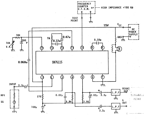
Number 1 ~ the ubiquitous 1310, which comes with various prefixes, BA, CA, LM, MC depending who made it.
Difficult to actually find one now but there's the Texas Instruments equivalent SN76115N. Can be got from Cricklwood Electronics for (at time of writing) £2.00 each.
cricklewoodelectronics.com/
Only thing is as the Troughline MPX output is straight off the detector, which is high impedance, so some high impedance input buffer would then be needed as the input of the chip is 50k. This could be a cathode follower or a jFET (but if a valve CF, add protection Zeners across the input or something so the valve doesn't fry the chip with high Voltage surges when it powers up and down).
Notes ~ the subcarrier regenerator is a phase locked loop system derived from an on-chip 76 kHz oscillator. The 10k preset is used to adjust the frequency of the oscillator while 19 kHz, derived by a divider, can be measured at pin 10. If not got a frequency counter then if I remember rightly can do it "by ear" by tuning to a weak FM station that's broadcasting stereo, and twiddling until the LED lights up.
The lamp could be an actual filament lamp, e.g. one of Rapid's 16V 1W panel indicator jobbies available in red, green and orange.
Power supply should be regulated and smoothed obviously and capable of at least 100mA. Oh and 12 - 15V range would be good.
Note also the L & R outputs are at DC so coupling caps will be needed. For low pass filters (L.P.F.) see further on....
Sat Oct 16, 2010 5:47 pm
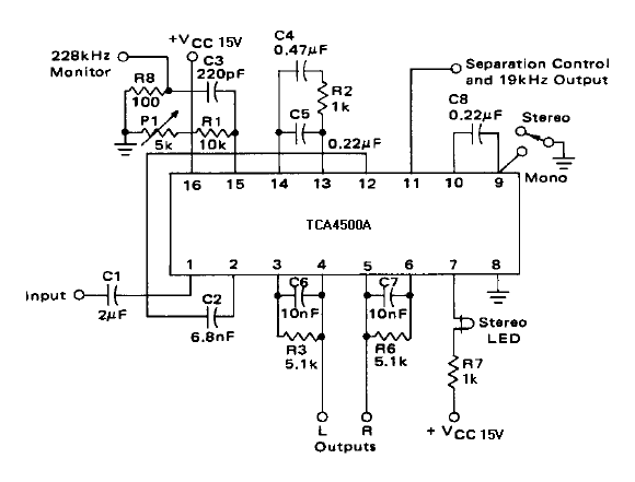
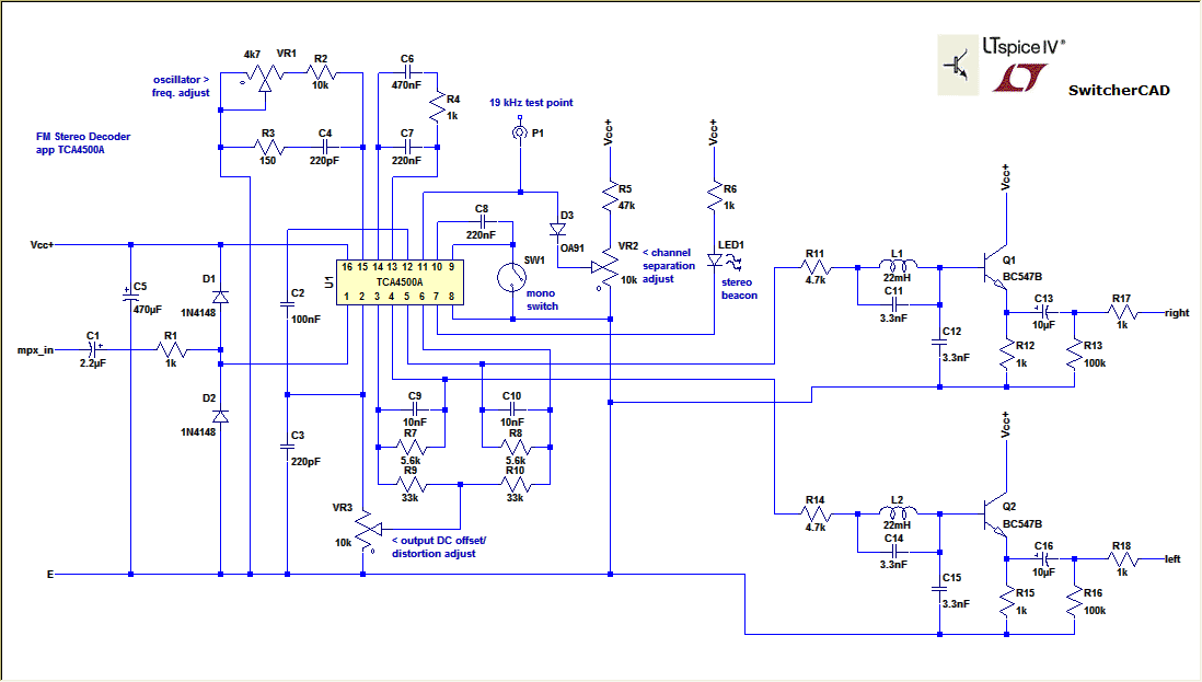
Number 2 ~ the Motorola alternative, TCA4500A, very much the same sort of thing but in a 16-pin package. £1.50 each from Cricklewoods (at time of writing).
cricklewoodelectronics.com/
Apart from getting the 19 kHz test from pin 11, this pin also controls stereo separation. If connected to ground through a diode (makes 0.7V on the pin) it's virtually made mono. If left open circuit (I think), stereo. Or even variable in between apparently. However stereo can be defeated by switching pin 9 to ground.
I expect you could put either together on a bit of stripboard for not much more than a tenner.
Sat Oct 16, 2010 6:12 pm
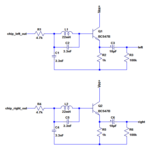
An example Low Pass Filter borrowed from another TCA4500 datasheet. I think it's to take out the ultrasonics without compromising the audio bandwidth. Not sure what the chip output DC is to be honest but the idea is use it to bias the emitter followers.
Edit: sorry I amended this 'cause I looked up my reactance chart and found 22mH and 3.3nF by themselves form a tuned circuit at 19 kHz, not 22mH & 3.3nF + paralleled with 2 x 3.3nF in series. So took out the end pair of the 3.3nF.
FYI, the tuned circuit presents a high impedance @ 19 kHz, with considerable attenuation after it, like a very sharp notch filter. Residual subcarrier component is reduced by the preceding 4.7k & 3.3nF to ground, I presume that's what it's for.
Sun Oct 17, 2010 12:43 am
Think I'd try to keep it simple. Bear in mind this stereo encoding method was dreamed up in the early 1960's so it ain't all that complicated. Clever, I grant you, getting it all in one signal.
Have you seen this? Check out the diagram about half way down, 'Typical spectrum of composite baseband signal'
wikipedia.org/wiki/FM_broadcasting
Speaking of decoders I think there's something wrong with my Ambit one, or else it's shite. This is not a new observation, I noticed it when first using it years ago, maybe one reason why it ended up in the attic.
Basically strong bass is wavery like it's got tremelo, complex midrange sounds can get slurred and it sounds like the "presence" and treble is artificially enhanced. Now that I can force mono, mono sounds terrific in comparison (despite going through the same chips).
Ambit Decoder
The Ambit decoder module does not use a 'normal' purpose designed FM stereo decoder chip, but a chipset comprising of a separate PLL, plus, erm, something else. As I said I've lost the original info so don't know what these chips are now. Either it was a nice idea but doesn't work, or, there's a fault on the module. (?)
There's a number of presets on it so maybe it's a question of setting up except I've lost the information about it. If there was any of that sort as it was a buy as ready-built module (aka, don't fiddle)
I ordered some TCA4500 today, so might have a go making my own version see if that's any different
Sun Oct 17, 2010 3:00 pm
Slightly more sophisticated circuit imminent
Mon Oct 18, 2010 3:06 pm
Ta-da!!
Mon Oct 18, 2010 3:09 pm
Going to have a go making this and try it in the Ambit tuner so got some bits on order.
Total parts list is:
Ref. Mfg. Part No. Description
C1 Panasonic -- capacitor, 2.2µF, 50V
C2 -- -- capacitor, 100nF, 100V
C3 -- -- capacitor, 220pF, 160V
C4 -- -- capacitor, 220pF, 160V
C5 Panasonic -- capacitor, 470µF, 25V
C6 -- -- capacitor, 470nF, 100V
C7 -- -- capacitor, 220nF, 100V
C8 -- -- capacitor, 220nF, 100V
C9 -- -- capacitor, 10nF, 100V
C10 -- -- capacitor, 10nF, 100V
C11 -- -- capacitor, 3.3nF, 100V
C12 -- -- capacitor, 3.3nF, 100V
C13 Panasonic -- capacitor, 10µF, 25V
C14 -- -- capacitor, 3.3nF, 100V
C15 -- -- capacitor, 3.3nF, 100V
C16 Panasonic -- capacitor, 10µF, 25V
D1 -- 1N4148 diode
D2 -- 1N4148 diode
D3 -- OA91 germanium diode (Rapid)
L1 -- -- inductor, 22mH (RS or Rapid low current ferrite choke)
L2 -- -- inductor, 22mH (")
LED1 LED or panel lamp 16V 1W (Rapid for latter)
P1 PCB pin
Q1 -- BC547B bipolar transistor
Q2 -- BC547B bipolar transistor
R1 -- -- resistor, 1K, 5%, .5W
R2 -- -- resistor, 10K, 5%, .5W
R3 -- -- resistor, 150, 5%, .5W
R4 -- -- resistor, 1K, 5%, .5W
R5 -- -- resistor, 47K, 5%, .5W
R6 -- -- resistor, 1K, 5%, .5W (not if 16V lamp used)
R7 -- -- resistor, 5.6K, 5%, .5W
R8 -- -- resistor, 5.6K, 5%, .5W
R9 -- -- resistor, 33K, 5%, .5W
R10 -- -- resistor, 33K, 5%, .5W
R11 -- -- resistor, 4.7K, 5%, .5W
R12 -- -- resistor, 1K, 5%, .5W
R13 -- -- resistor, 100K, 5%, .5W
R14 -- -- resistor, 4.7K, 5%, .5W
R15 -- -- resistor, 1K, 5%, .5W
R16 -- -- resistor, 100K, 5%, .5W
R17 -- -- resistor, 1K, 5%, .5W
R18 -- -- resistor, 1K, 5%, .5W
SW1 Switch
U1 TCA4500A (Cricklewood Electronics)
VR1 enclosed horizontal preset 4.7k
VR2 enclosed horizontal preset 10k or front panel pot
VR3 enclosed horizontal preset 10k
-- stripboard as appropriate
-- 16-DIL IC socket
All resistors = carbon
Electrolytics = Panasonic from RS
All non-electrolytics = mylar type (normally green enamelled) from Cricklewood Electronics
EXCEPT C3, C4 = 160V polystyrene or mica (RS, Rapid or Hi-Fi Collective)
Mon Oct 18, 2010 3:23 pm
Oh yeah the recommended power supply is 12 - 15V regulated, 100mA minimum capability.
The input impedance is 50k I believe; if adding to a Troughline probably needs a buffer at the input for the detector.
Alternatively, you could bridge the 470k de-emphasis resistor, and remove the following 100pF filter cap, which feeds the grid of the audio output CF (ECF80 triode). That's how the Troughline Stereo does it. Then it'll come out on the mono lead.
Tue Oct 19, 2010 12:49 am
Had a measure up in the Ambit tuner to find out how big the the original decoder board is. Also to figure out what all the connecting wires do.
Isolated the supply, earth, audio L & R out, stereo LED, and the thing that does the stereo switching threshold level.
That left me with an orange wire and a brown wire. One of them has the MPX audio on it. Don't know what the other one does.
Upon close examination of the IF board turns out it's the brown wire with the MPX. It comes out a chip, through a RC filter then a coil.
The orange wire connects to - something, via a 22k resistor. This rings a distant bell and I don't I think I understood what it was for at the time of assembling it, probably something to try see what it does. Maybe I forgot to try it the other way, I dunno.
Well as an experiment I disconnected it, still works so proves the brown is indeed the output. However the strangely artificially enhanced channel separation seems to have gone! Hmmm....
Tue Oct 19, 2010 11:53 pm
Started what was meant to be a quick-ish layout of the board, ended up putting most everything on until it got really quite tedious.
Forgot to measure the original mounting pillar positions so should do that next really, then fire up the soldering gun. In theory....
Then there is of course the "wait 'til next day idiot check", as what I've done tonite could in reality be all a massive coke-up
Wed Oct 20, 2010 5:44 pm
Adapted the board to fit in it's final resting place (at least that is the plan, but anything is subject to change), all the comps are on just needs soldering.
He sez hopefully....
Been wondering what to test it with, I guess you could put 19 kHz sine into it to represent a pilot tone, if freq. is accurate you use that to trim the oscillator and see if the indicator LED lights up. According to datasheet minimum pilot tone level to switch over is 10 - 12 mV.
The audio outputs would then be like silence in stereo, that is, silent mono and no sub-carrier because of course the L & R channels aren't different!
Alternatively, any audio band signal should come out as mono only on both channels, as there's no pilot so no regenerated sub-carrier either.
Thu Oct 21, 2010 10:56 pm
Got the thing running tonight.
No puffs of the magic smoke released or nasty burning smells so either there's a supply connection missing, or it's working.
Well whaddya know, it's all working. Volts of the necessary prerequisite values are where they are supposed to be. So far so good.
'Scope onto 19 kHz monitor pin. Ve haff an oscillation going on. Majik.

Even better, my Fluke 83 can measure it's freguency. Twiddle for 19 kHz, +/– a couple of percent. The 'scope timebase is very slightly off but that's not surprising.
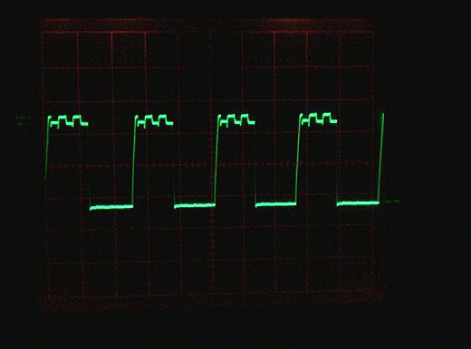
It's 1.5V peak-peak superimposed onto what measures as an average 4V DC. The small stuff on the top lines is the 76 kHz oscillator rippling through I presume; this is followed by a divide by 2 stage to make the 38 kHz (the regenerated sub-carrier) and another divide by 2 stage to get this 19 kHz.
Thu Oct 21, 2010 11:07 pm
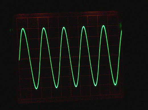
Next, stuff a 1 kHz sine wave through it, see if it comes out the other end. Indeed it does. Tick

Two things become apparent.
1. The DC offset preset thingy also affects gain. Max. is achieved when the preset is down to 0V, that is max. DC offset (makes outputs more positive, but not by a huge amount).
Initially I've set so that the AC output levels equal the AC input level at pin 1.
2. Much over half a Volt peak of input and it starts going pear-shaped, with ultrasonic internal frequencies breaking through.
It was therefore prudent, I thought, to add an input level control preset in case the MPX source is indeed a mite on the strong side. This done I could put 1V in, as an arbitrary yardstick level, and adjust for 0.5V out. 100k preset is OK.
Below is an example of 1 kHz output:
Thu Oct 21, 2010 11:37 pm
Next, see if it will detect a pilot tone. I found and croc leaded up a test LED.
Wind up the sig. gen. as appropriate, voila, then there was light.
Blinding as well (on axis) I was using one of those extra bright white LED's.
The capture range is fairly narrow but will "track" the sig gen when varied and keeping in that range.
The 19 kHz tuned circuit traps are certainly useful, because when the thing captures, a small amount of the 38 kHz sub-carrier appears on the outputs as well, this "mush" is reduced to 10mV peak by the added filters. Mind you on reflection the 19 kHz going in was 600mV, I forgot it's only supposed to be about 10% of the total mono audio signal input amplitude. Hey ho – anyway works at 60mV as well, datasheet says 10 - 12mV.
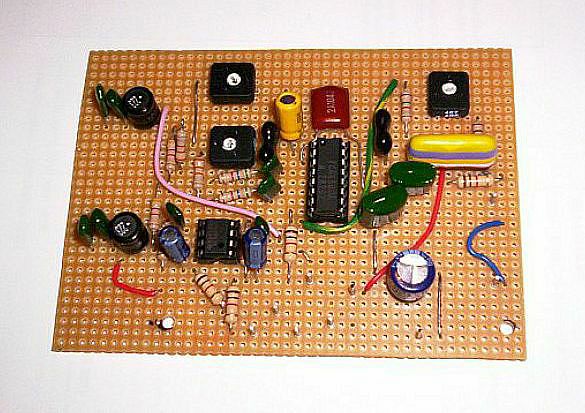
Piccies of the TDA4500 decoder board:
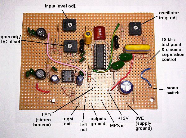
Note a design change, for this application I am using a NE5532 dual op-amp chip for the output buffers, as it happens the decoder outputs DC, which also biases the op-amps, can be quite low, fortunately the op-amps have a wide output swing capability to accommodate it. Haven't seen any clipping yet, the ultrasonic break-though problem occurs way before that happens.
Board size is 110 x 80mm to fit the Ambit tuner, was 95mm wide but the two edge tracks on each side of the largish Vero board I'd bought didn't have no holes in them so were a bit redundant. (This board came from RS and is actually by Vero.)
Think it had been on-the-shelf for a while as was a bit oxidised despite being in a "sealed" plastic bag, this made it a bit difficult to solder sometimes. Should have been scrubbed with some scouring powder first ~ assuming I've still got any

Fri Oct 22, 2010 12:22 am
The Circuit
as final, with op-amps outputs: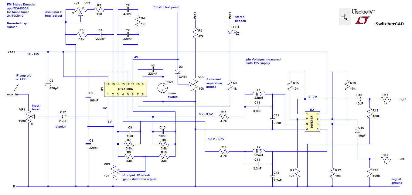
Addendum
The op-amps were latterly reconfigured for a Voltage gain of X2 by virtue of adding the 10k resistors, this makes the output nearer to CD level etc.
Note ~ for best sound quality, C9, 10, 12, 15 are polystyrene, all other non-electrolytics remain as mylar, except C3, 4 = mica, C6 = polyester; C13, 16 are Panasonic low ESR electrolytic; C17 = good quality bipolar electrolytic (e.g. for speaker crossovers); all resistors in the signal paths are carbon film, or can be carbon composite.
Note ~ for best sound quality, C9, 10, 12, 15 are polystyrene, all other non-electrolytics remain as mylar, except C3, 4 = mica, C6 = polyester; C13, 16 are Panasonic low ESR electrolytic; C17 = good quality bipolar electrolytic (e.g. for speaker crossovers); all resistors in the signal paths are carbon film, or can be carbon composite.
Fri Oct 22, 2010 8:33 pm
Making real noises!

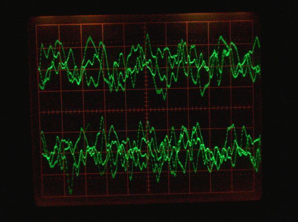
Some choral singing thingy on Classic FM early this afternoon. Here, amplitude is relative to 200mV per division of graticule.
However....
Modifications ~ am I hyper-fussy or what?
Firstly, output seems a bit low. VR4 (see previous schematic) can be whacked right up (in this particular case), but output still a bit low. I did wonder if this might occur actually. Good news is, adoption of the dual op-amp on the o/p means it's a very simple matter of boosting the output X2. Two pairs of 10k resistors strategically arranged, job's a good 'un. Also, it amplifies the decoder DC as well so the op-amp output pins can be more nearer half supply Volts.
Secondly, on ack-chewl listening to it, treble seems a teensiest-weeniest bit of a smidgeon dull. Experiments with capacitors commenced (which amounted to holding the points of the leads onto different bits of the circuit while it was running, and listening for any difference), and the outcome suggested that:
A. input cap C17 might do with being shunted with an extra something, 220nF mylar seems good.
B. how about if C12 & 15 were removed? Snip-snip here, snip-snip there - hmmm!! I would venture to suggest that it does help. Awlrighty then. Mind you we're talking a gnat's toenail clipping's worth of difference TBH, nevertheless I've had time to get used to it throughout the remainder of the afternoon and this evening and the noises it makes ain't too shabby at all must be said.
It's quite different to the original Ambit decoder ~ that had a sort of "hyperactive" treble tendency ~ not particularly loud or too obviously accentuated, just "in yer mush" with it occasionally, depending what's playing. It can be demonstrated if compared directly with playing CD's of a similar kind if not the same music.
This one I would describe as "more natural sounding".
Unlike the Ambit board it is not controlled by the IF amp vis-a-vis signal level determining a threshold for workable stereo mode, so a mono switch is a must, otherwise there's too much hiss on weaker stations so must resort to mono mode.
I also cobbled up the channel separation thingy using the 10k pot already put on the front panel, this connects to pin 11 of the TCA4500 (19 kHz test pin) via a OA91 germanium diode, cathode end towards the control pot. Whaddya know it works....
The top of the pot connects to +12V via a dropper resistor, to cut a long story short, below a certain Voltage point, the closer the pot wiper is to 0V the left – right channels close in until a virtual mono is achieved at the bottom of the track.
Fri Oct 22, 2010 8:50 pm
More photos ~ first the underside, although the extra 10k resistors hadn't been added yet. Bit involved, not surprising took 2 days to complete really.

In situ, this time with the extra comps added:


Fri Oct 22, 2010 9:01 pm
Appendix ~ the hiss that can occur on weaker stations when stereo working is not as acute as it is with the original Ambit decoder. Which is interesting.
Fri Oct 22, 2010 9:16 pm
I am now onto BBC Essex local transmitter, must say it does sound much more "got it together" and sort of solid than did the Ambit decoder, and no more 'wobbly bass'. And this Ambit decoder was supposed to be the wasp's ankles in its time!
 ...?
...?Fri Oct 22, 2010 9:41 pm
Just to add, nice round solid bass beat from the DIY decoder, in comparison the Ambit version is all warbly and tremulant, actually, it was always a bit like that if memory serves, and which I have typically blamed on a radio signal problem (including just recently), so what that's all about I've no idea!

Sat Oct 23, 2010 2:57 pm
Modifications!
Don't panic Mr. Mainwaring! Only little ones
Listening to it last into the wee small hours I thought it's pretty good, but wondered about the overall tone balance.
For example, in the basic application circuit R7 & 8 are 5.1k, in the "improved version" I was looking at this is upped slightly to 5.6k. Presumably for a tad more gain. However the shunt caps remain 10nF, shirley if the resistors are increased in value slightly, then the shunt cap values should be reduced in proportion?
As an experiment I changed C9 & 10 to 8.2nF.
Also, reinstate C12 & 15 as 1nF, so the 19 kHz trap filter has a better chance of working.
First noticeable thing, the volume control is not as high as yesterday, so obviously output level is more lifted from the midrange upward. How this matches the bass end remains to be seen. Or heard rather.
I am still evaluating!
Sun Oct 24, 2010 12:35 am
All change!
It's all go here I tell you
Right so finally got to the bottom of the "missing treble" mystery. The output capacitors are not letting it through good enough! Ergo, bridging them with an extra something like 10nF, and it's all totally different. Then of course it's too bright hence C9, 10, 12, 15 needed reverting back to what they were originally. Above schematic is amended to reflect this.
It now sounds very similar to the Leak Troughline, which is saying something.
Half an hour ago was listening to some very nice guitar music that ended this week's Paul Barnes' jazz and big band show, excellent stuff.
Sun Oct 24, 2010 12:10 pm
Well I dunno either my ears have changed or the programming has changed. 'Cause last night and today everything is way too bright. So I've just took out all the HF strapping caps leaving just the 'lytics behind.
Everything is sitll plenty sharp enough so what was going on before I dunno.
PS - BBC Essex is transmitting songs in stereo today!
Maybe they only do it on Sundays
Tue Oct 26, 2010 4:19 pm
Useful tip number #5.....
The 10k trimmer VR3 does indeed seem to do something vis a vis distortion or sound quality.
The initial brightness I was complaining about previously looks like had something to do with this. Could indeed be excessive harmonic overtones (harmonic distortion).
Was playing with different positions last night, seems somewhere around the centre of the track is best.
Hitherto I had also increased C12, 15 to 4.4nF, which filled out the midrange and bass better. I.e. knocked the treble off a tad more. Guess you'll have to experiment with these to suit personal taste. [Edit: Subsequently restored to 3.3nF.]
Tue Oct 26, 2010 4:21 pm
PS a secondary effect of getting VR3 right is lower amounts of hiss on weak stations ~ or so it seems.
Tue Jan 18, 2011 2:55 pm
Update:
Use of polystyrene caps for C9, C10, C12, C15 may be preferred to the green mylars (or I do), treble is noticably smoother with the polystyrenes.
The band stop filter tuning caps C11, 14) may remain as mylar, as audio frequencies should mostly pass through the coil. Note the optimum value is 2.2nF + 1nF in parallel. 3.3nF might be used but looks like it will detune it slightly downward. (Should be 19 kHz).
Conclusion
The Ambit tuner modified as described has been used practically daily ever since and is still giving excellent performance.